Mitsubishi Pajero Pinin. Manual - part 150
 

  Index      Mitsubishi     Mitsubishi Pajero Pinin - service repair manual 2001 year


Search            


Content   ..  148  149  150  151   ..


Mitsubishi Pajero Pinin. Manual - part 150


ENGINE ELECTRICAL – 

Ignition System

16-30

SPARK PLUG CHECK AND CLEANING 

CAUTION
1.

Do not adjust the gap for iridium plugs.

2.

The iridium tips may become damaged when iridium
plugs are cleaned. Accordingly, if the plugs are sooty
and need to be cleaned, use a plug cleaner in order
to protect the terminals, and do not clean for more
than 20 seconds. Tools such as wire brushes must
never be used.

3.

The terminals of iridium plugs may become blackened,
even when the plugs are functioning normally.
However, the carbon which is deposited onto these
plugs burns off more easily than for conventional
spark plugs, so such blackening is not normally a
problem. Measure the insulation resistance of the
spark plug to judge if the plug is still usable or not.

(1) Check the plug gap, and replace the plug if the gap is

greater than the limit value.

Standard Valve : 0.5 – 0.6 mm

Limit : 0.75 mm

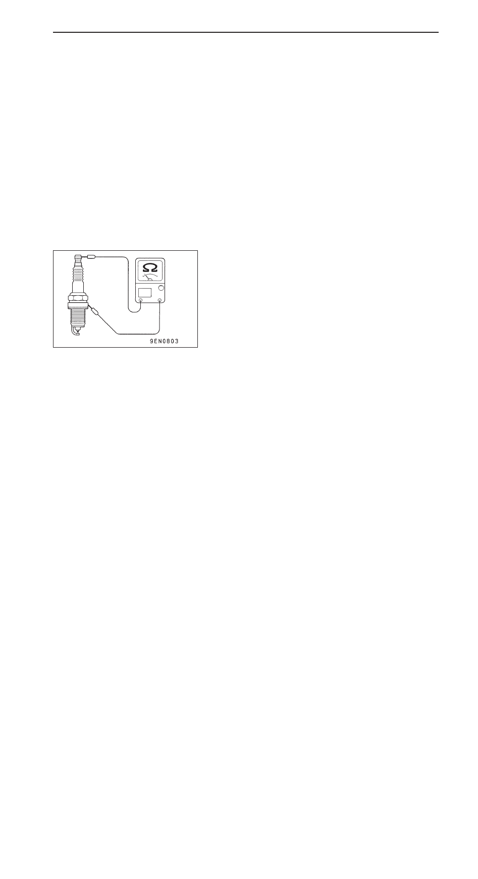
(2) Measure the insulation resistance of the spark plug, and

replace the plug if the resistance is below the limit value.

Limit : 1 M

CAMSHAFT POSITION SENSOR CHECK 

Refer to GROUP 13A – Troubleshooting.

CRANK ANGLE SENSOR CHECK

Refer to GROUP 13A – Troubleshooting.

DETONATION SENSOR CHECK

Check the detonation sensor circuit if self-diagnosis code,
No. 31 is shown.

NOTE
For information concerning the self-diagnosis codes, refer to
GROUP 13A – Troubleshooting .

ENGINE ELECTRICAL – 

Ignition System

16-31

IGNITION COIL

REMOVAL AND INSTALLATION

Pre-removal and Post-installation Operation

D

Engine Cover Removal and Installation

D

Resonance Tank  Removal and Installation 
(Refer to GROUP 15.)

D

Air Cleaner Assembly and Air Intake Hose Removal
and Installation

25 Nm

1

3

2

10 Nm

Disassembly steps

1. Ignition Coil Connector
2. Ignition Coil
3. Spark Plug

ENGINE ELECTRICAL – 

Ignition System

ENGINE ELECTRICAL – 

Ignition System

16-32

CRANK ANGLE SENSOR

REMOVAL AND INSTALLATION

Pre-removal and Post-installation Operation
Timing Belt Front Lower Cover Removal and Installation
(Refer to GROUP 11.)

9 Nm

Crank angle sensor

CAMSHAFT POSITION SENSOR 

REMOVAL AND INSTALLATION

Pre-removal and Post-installation Operation
Engine Cover Removal and Installation

Camshaft
position
sensor

9 Nm

ENGINE ELECTRICAL – 

Ignition System

16-33

DETONATION SENSOR 

REMOVAL AND INSTALLATION

Pre-removal and Post-installation Operation

D

Engine Cover Removal and Installation

20 – 25 Nm

10 – 12 Nm

2

1

10 – 12 Nm

Disassembly steps

1. Water pipe clamp

A

A

" "

A

A

2. Detonation sensor

REMOVAL SERVICE POINT

A

A

"

DETONATION SENSOR REMOVAL

INSTALLATION SERVICE POINT

"

A

A

DETONATION SENSOR INSTALLATION

MD998773


Content   ..  148  149  150  151   ..