Mitsubishi Pajero Pinin. Manual - part 129


  Index      Mitsubishi     Mitsubishi Pajero Pinin - service repair manual 2001 year


Search            


Content   ..  127  128  129  130   ..


Mitsubishi Pajero Pinin. Manual - part 129


MPI <4G9> – 

On-vehicle Service

13C-102

CONTROL RELAY AND FUEL PUMP RELAY
CONTINUITY CHECK

Battery voltage

Terminal No.

y

g

1

2

3

4

Not supplied

Supplied

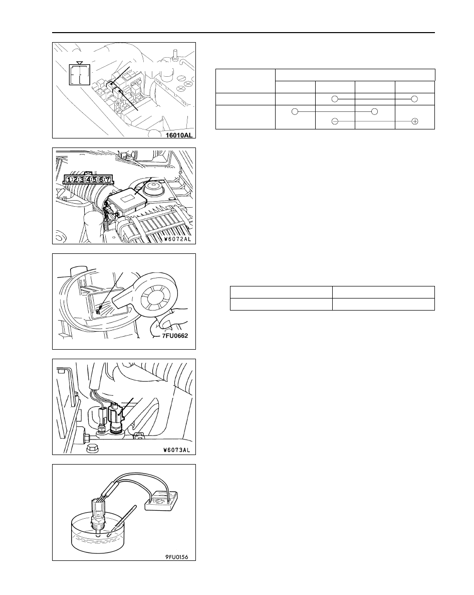
INTAKE AIR TEMPERATURE SENSOR CHECK

1.

Disconnect the air flow sensor connector.

2.

Measure resistance between terminals 5 and 6.

Standard value:

13  – 17 k

 (at –20

_

C)

5.7  – 6.7 k

 (at 0

_

C)

2.3  – 3.0 k

 (at 20

_

C)

1.0  – 1.5 k

 (at 40

_

C)

0.56  – 0.76 k

 (at 60

_

C)

0.30  – 0.42 k

 (at 80

_

C)

3.

Measure resistance while heating the sensor using a hair
drier.

Normal condition:

Temperature (

_

C)

Resistance (k

)

Higher

Smaller

4.

If the value deviates from the standard value or the
resistance remains unchanged, replace the air flow sensor
assembly.

ENGINE COOLANT TEMPERATURE SENSOR
CHECK

Caution
Be careful not to touch the connector (resin section) with
the tool when removing and installing.

1.

Remove the engine coolant temperature sensor.

2.

With temperature sensing portion of engine coolant
temperature sensor immersed in hot water, check
resistance.

1

4

3

2

Equipment side connector

Control relay

Fuel pump relay

Equipment side
connector

Air flow sensor

Intake air temperature
sensor

Engine coolant
temperature sensor

MPI <4G9> – 

On-vehicle Service

13C-103

Standard value:

14  – 17 k

 (at –20

_

C)

5.1  – 6.5 k

 (at 0

_

C)

2.1  – 2.7 k

 (at 20

_

C)

0.9  – 1.3 k

 (at 40

_

C)

0.48  – 0.68 k

 (at 60

_

C)

0.26  – 0.36 k

 (at 80

_

C)

3.

If the resistance deviates from the standard value greatly,
replace the sensor.

4.

Apply sealant to threaded portion.

Specified sealant:

3M Nut Locking Part No.4171 or equivalent

5.

Install the engine coolant temperature sensor and tighten
it to the specified torque.

Tightening torque: 29 

±

 9 N·m

THROTTLE POSITION SENSOR CHECK

1.

Disconnect the throttle position sensor connector.

2.

Measure the resistance between the throttle position
sensor side connector terminal 1 and terminal 4.

Standard value: 3.5 – 6.5 k

3.

Measure the resistance between the throttle position
sensor side connector terminal 2 and terminal 4.

Normal condition:

Throttle valve slowly open
until fully open from the idle
position

Changes smoothly in
proportion to the opening
angle of the throttle valve

4.

If the resistance is outside the standard value, or if it doesn’t
change smoothly, replace the throttle position sensor.

NOTE
For the throttle position sensor adjustment procedure, refer
to P.13C-96.

OXYGEN SENSOR CHECK 
<Oxygen sensor (front)>

1.

Disconnect the oxygen sensor connector and connect the
special tool (test harness) to the connector on the oxygen
sensor side.

2.

Make sure that there is continuity (4.8 – 8.0 

 at 20

_

C)

between terminal 1 (red clip of special tool) and terminal
3 (blue clip of special tool) on the oxygen sensor connector.

Equipment
side connector

Throttle position
sensor

3

4

1

2

Equipment side connector

Oxygen sensor (front)

MPI <4G9> – 

On-vehicle Service

MPI <4G9> – 

On-vehicle Service

13C-104

3.

If there is no continuity, replace the oxygen sensor.

4.

Warm up the engine until engine coolant is 80

_

C or higher.

5.

Use the jumper wire to connect terminal 1 (red clip) of
the oxygen sensor connector to the battery (+) terminal
and terminal 3 (blue clip) to the battery (–) terminal.

Caution
Be very careful when connecting the jumper wire;
incorrect connection can damage the oxygen sensor.

6.

Connect a digital voltage meter between terminal 2 (black
clip) and terminal 4 (white clip).

7.

While repeatedly racing the engine, measure the oxygen
sensor output voltage.

Standard value:

Engine

Oxygen sensor
output voltage

Remarks

When
racing the
engine

0.6 – 1.0 V

If you make the air/fuel ratio
rich by racing the engine
repeatedly, a normal oxy-
gen sensor will output a
voltage of 0.6 – 1.0 V.

8.

If the sensor is defective, replace the oxygen sensor.

NOTE
For removal and installation of the oxygen sensor, refer
to GROUP 15 – Exhaust Pipe and Main Muffler.

<Oxygen sensor (rear)>

1.

Disconnect the oxygen sensor connector and connect the
special tool (test harness) to the connector on the oxygen
sensor side.

2.

Make sure that there is continuity (11 – 18 

 at 20

_

C)

between terminal 1 (red clip of special tool) and terminal
3 (blue clip of special tool) on the oxygen sensor connector.

Red

Oxygen
sensor
equipment
side connector

Blue

MD998464

Jumper
wire

Black

Red

White

MD998464

Blue

1

2

3

4

Equipment side connector

Oxygen sensor (rear)

MPI <4G9> – 

On-vehicle Service

MPI <4G9> – 

On-vehicle Service

13C-105

3.

If there is no continuity, replace the oxygen sensor.

4.

Warm up the engine until engine coolant is 80

_

C or higher.

5.

Use the jumper wire to connect terminal 1 (red clip) of
the oxygen sensor connector to the battery (+) terminal
and terminal 3 (blue clip) to the battery (–) terminal.

Caution
Be very careful when connecting the jumper wire;
incorrect connection can damage the oxygen sensor.

6.

Connect a digital voltage meter between terminal 2 (black
clip) and terminal 4 (white clip).

7.

While repeatedly racing the engine, measure the oxygen
sensor output voltage.

Standard value:

Engine

Oxygen sensor
output voltage

Remarks

When
racing the
engine

0.6 – 1.0 V

If you make the air/fuel ratio
rich by racing the engine
repeatedly, a normal oxy-
gen sensor will output a
voltage of 0.6 – 1.0 V.

8.

If the sensor is defective, replace the oxygen sensor.

NOTE
For removal and installation of the oxygen sensor, refer
to GROUP 15 – Exhaust Pipe and Main Muffler.

Red

Oxygen
sensor
equipment
side connector

Blue

MD998464

Jumper
wire

Black

Red

White

MD998464

Blue


Content   ..  127  128  129  130   ..