Mitsubishi Pajero Pinin. Manual - part 55
 

  Index      Mitsubishi     Mitsubishi Pajero Pinin - service repair manual 2001 year


Search            


Content   ..  53  54  55  56   ..


Mitsubishi Pajero Pinin. Manual - part 55


GDI – 

Troubleshooting

13A-86

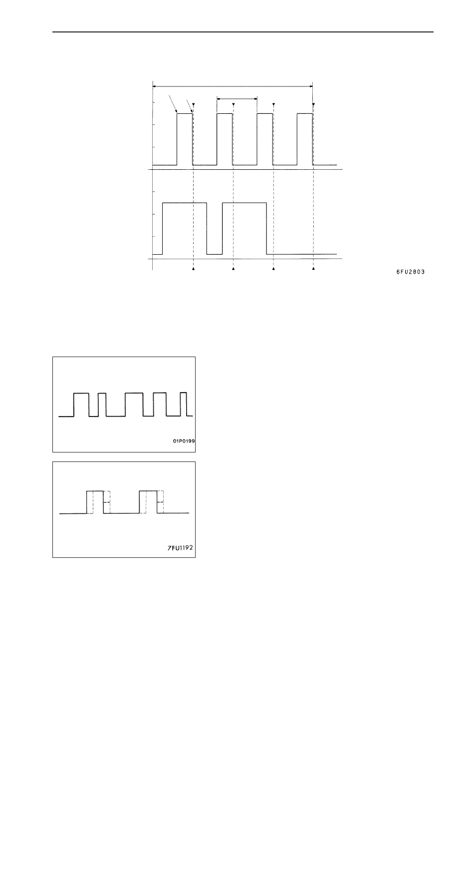
Standard wave pattern

Crank angle 
sensor output
wave pattern

(V)

75

_

BTDC

2 engine revolutions 
(1 camshaft revolution)

5

_

BTDC

The time (cycle time) T is
reduced when the engine
speed increases

0

Camshaft posi-
tion sensor out-
put wave pat-
tern

TDC: Top dead centre

No. 1
TDC

No. 3 TDC

No. 

4

TDC

No. 2
TDC

Time

0

T

4

4

Wave Pattern Observation Points

Check that cycle time T becomes shorter when the engine speed increases.

Examples of Abnormal Wave Patterns

D

Example 1

Cause of problem

Sensor interface malfunction

Wave pattern characteristics

Rectangular wave pattern is output even when the engine
is not started.

D

Example 2

Cause of problem

Loose timing belt
Abnormality in sensor disk

Wave pattern characteristics

Wave pattern is displaced to the left or right.

GDI – 

Troubleshooting

13A-87

INJECTORS AND INJECTOR OPEN CIRCUIT CHECK
SIGNAL

Measurement Method

1.

Connect the analyzer special patterns pickup to terminal
1 (No.1 injector) of the engine-ECU connector.

2.

Connect the analyzer special patterns pickup to terminal
96 (injector open circuit check signal) of the engine-ECU
connector.

3.

After checking terminal 1, check terminal 9 (No.2 injector),
terminal 24 (No.3 injector) and terminal 2 (No.4 injector).

Standard Wave Pattern

Observation conditions

Function

Special pattern

Pattern height

Low

Pattern selector

Display

Engine r/min

Idle speed

Standard wave pattern

4

0

8

4

0

(V)

Injector
open circuit
check+
signal

Injector
drive signal

(ms)

Wave Pattern Observation Points

D

Check that the injector drive time is identical to the time
displayed on the MUT-

II

.

D

Check that the injector signals become greatly extended
but soon return to their normal wave length when the
engine is suddenly raced.

D

Check that the injector open circuit check signal is
synchronized with each rising portion of the injector drive
signal.

Special patterns
pickup

Analyzer

Normal wave
pattern

GDI – 

Troubleshooting

13A-88

IGNITION COIL AND POWER TRANSISTOR

Power transistor control signal

Measurement Method

1.

Disconnect the ignition coil connector, and connect the
special tool (test harness: MB991658) in between. (All
terminals should be connected.)

2.

Connect the analyzer special patterns pickup to terminal
3 of each ignition coil connector in turn.

Alternate Method (Test harness not available)

1.

Connect the analyzer special patterns pickup to
engine-ECU terminal 3 (No. 1 ignition coil), terminal 13
(No. 2 ignition coil), terminal 12(No. 3 ignition coil), terminal
4 (No. 4 ignition coil) respectively.

Standard Wave Pattern

Observation condition

Function

Special patterns

Pattern height

Low

Pattern selector

Display

Engine r/min

Approx. 1,200 r/min

Standard wave pattern

Crank angle 
sensor output
wave pattern

Power transistor
control signal 
wave pattern

(V)

Compression top dead center

θ

: Spark advance angle

Ignition period

OFF

Dwell section

Time

θ

T

4

0

0

T: Crank angle

T1

ON

T1: Time calculated by engine-ECU

Special
patterns
pickup

Analyzer

GDI – 

Troubleshooting

13A-89

Wave Pattern Observation Points

Point:

Condition of wave pattern build-up section and maximum voltage (Refer to abnormal wave pattern

examples 1 and 2.)

Condition of wave pattern build-up section and maximum voltage

Probable cause

Rises from approx. 2V to approx. 4.5V at the top-right

Normal

2V rectangular wave

Open-circuit in ignition primary circuit

Rectangular wave at power voltage

Power transistor malfunction

Examples of Abnormal Wave Patterns

D

Example 1

Wave pattern during engine cranking

Cause of problem

Open-circuit in ignition primary circuit

Wave pattern characteristics

Top-right part of the build-up section cannot be seen, and
voltage value is approximately 2V too low.

D

Example 2

Wave pattern during engine cranking

Cause of problem

Malfunction in power transistor

Wave pattern characteristics

Power voltage results when the power transistor is ON.

--- Normal wave pattern

2V

V

B

--- Normal wave pattern


Content   ..  53  54  55  56   ..