Mitsubishi Lancer. Manual - part 271


  Index      Mitsubishi     Mitsubishi Lancer - service repair manual 2006 year


Search            


Content   ..  269  270  271  272   ..


Mitsubishi Lancer. Manual - part 271


GENERAL INFORMATION

POWER PLANT MOUNT

32-2

GENERAL INFORMATION

M1321000100340

The engine mounting system employs the inertial 
axis four-point suspension method, which is field 
proven.

• The optimised locations of the front and rear roll 

mounts well distribute their loads thereby reduc-
ing engine idling vibrations.

• The fore-and-aft, liquid-filled engine mount of cyl-

inder type is adopted to reduce engine shake for 
improved riding comfort.

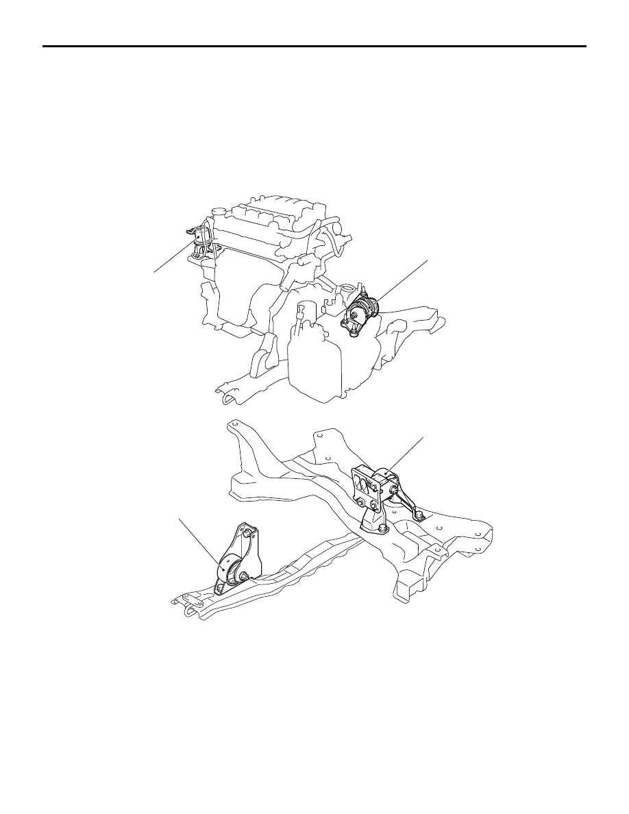
CONSTRUCTION DIAGRAM

AC107318

Y0290AU

AC303563

Engine mounting 
insulator

Transmission mounting insulator

Engine rear roll stopper bracket

Engine front roll stopper bracket

AB

SERVICE SPECIFICATION

POWER PLANT MOUNT

32-3

SERVICE SPECIFICATION

M1321000300333

Item

Standard value

Protruding length of stabilizer bar mounting bolt mm

22 

± 1.5

SPECIAL TOOL

M1321000600378

Tool

Number

Name

Use

AC106827

MB991897

Ball joint remover

Knuckle and tie rod end ball joint 
disconnection
NOTE: Steering linkage puller 
(MB990635 or MB991113) is also 
available to disconnect knuckle and 
tie rod end ball joint.

ENGINE MOUNTING

POWER PLANT MOUNT

32-4

ENGINE MOUNTING

REMOVAL AND INSTALLATION

M1321001100440

CAUTION

*: Indicates parts which should be initially tightened, and then fully tightened after placing the vehicle 
horizontally and loading the full weight of the engine on the vehicle body.

Pre-removal Operation
Raise the engine and transmission assembly until its weight 
is not applied to the insulator, and support it securely.

AC303999

AC303968

AC304304AB

<4G1>

<4G6>

44 ± 10 N·m*

67 ± 7 N·m*

2

N

3

44 ± 10 N·m*

67 ± 7 N·m*

2

N

3

12 ± 2 N·m

1

Removal steps 

1.

Pressure hose clamp <4G6>

2.

Self-locking nuts

3.

Engine Mounting Insulator

Removal steps (Continued)

TRANSMISSION MOUNTING

POWER PLANT MOUNT

32-5

TRANSMISSION MOUNTING

REMOVAL AND INSTALLATION

M1321001400430

CAUTION

*: Indicates parts which should be initially tightened, and then fully tightened after placing the vehicle 
horizontally and loading the full weight of the engine on the vehicle body.

Pre-removal Operation
• Raise the engine and transmission assembly until its 

weight is not applied to the insulator, and support it 

securely.

• Battery and Battery tray Removal

• Air Cleaner Removal (Refer to GROUP 15, Air Cleaner 

P.15-3

).

• Engine Rear Roll Stopper Bracket Removal (Refer to 

P.32-7

).

Post-installation Operation
• Engine Rear Roll Stopper Bracket Installation (Refer to 

P.32-7

).

• Air Cleaner Installation (Refer to GROUP 15, Air Cleaner 

P.15-3

).

• Battery and Battery tray Installation

AC303988

AC303989

AC304258

<M/T>

<A/T>

AB

82 ± 7 N·m*

47 ± 7 N·m*

82 ± 7 N·m*

47 ± 7 N·m*

1

1

2

2

2

2

Removal steps 

1.

Transmission mounting insulator

>>

A

<<

2.

Transmission mounting stopper


Content   ..  269  270  271  272   ..