Mitsubishi Lancer. Manual - part 262
AC303555AB
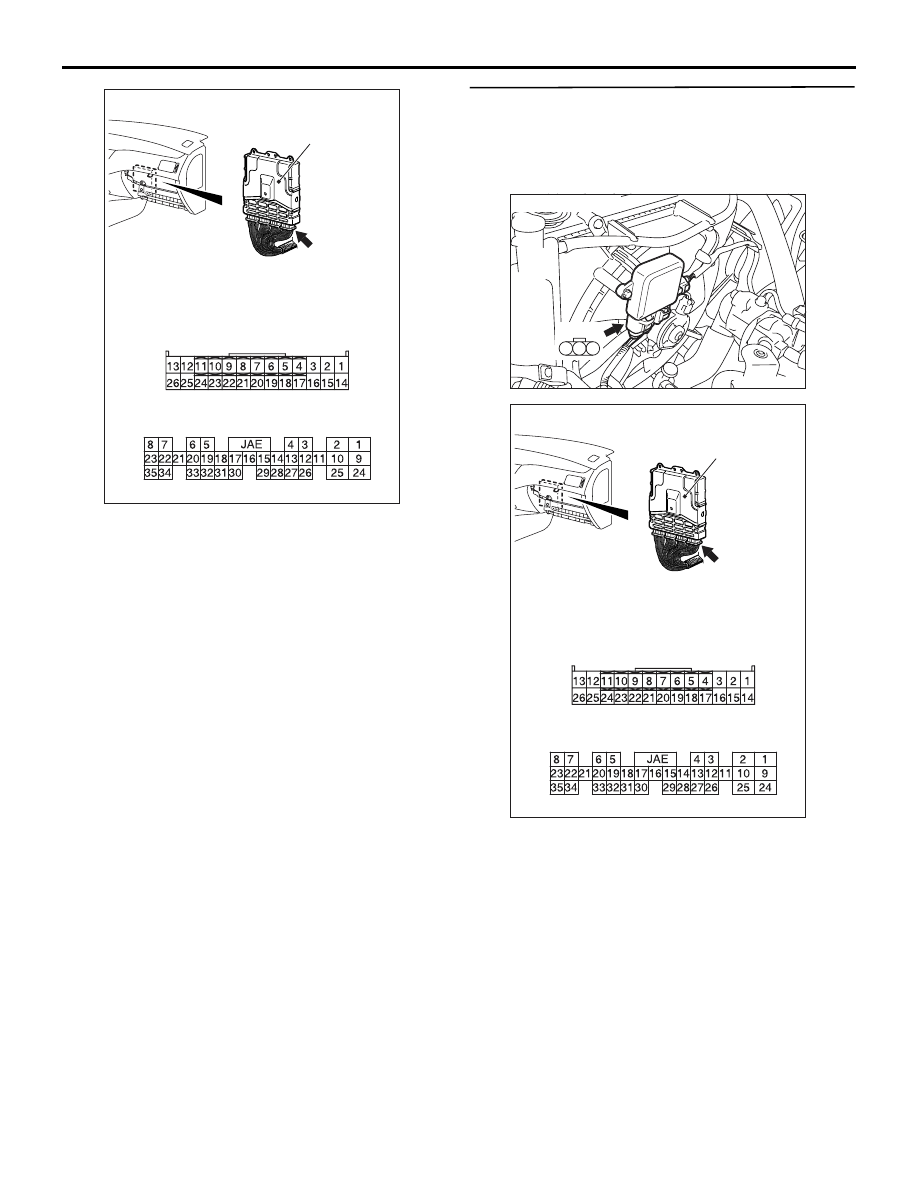
Connector: C-123 <M/T>, C-122 <A/T>
C-123 <M/T>
or
C-122 <A/T>
C-123 <M/T>
Engine-ECU <M/T> or
engine-A/T-ECU <A/T>
C-122 <A/T>
TROUBLESHOOTING
ENGINE COOLING
14-14
Q: Are these connectors in good condition?
YES :
Go to Step 21 .
NO :
Repair or replace the connector. Then go to
Step 24 .
STEP 21. Check the harness wire between
cooling fan motor drive control unit connector
A-18 terminal 2 and engine-ECU connector C-123
terminal 21 <M/T> or engine-A/T-ECU connector
C-122 terminal 18 <A/T>.
AC100293
A-18
3
2
1
Connector: A-18
AD
AC303555AB
Connector: C-123 <M/T>, C-122 <A/T>
C-123 <M/T>
or
C-122 <A/T>
C-123 <M/T>
Engine-ECU <M/T> or
engine-A/T-ECU <A/T>
C-122 <A/T>
Q: Are these harness wires in good condition?
YES :
Go to Step 22 .
NO :
Repair the damaged harness wire. Then go
to Step 24 .