Mitsubishi Lancer. Manual - part 208
STARTING SYSTEM
ENGINE ELECTRICAL
16-24
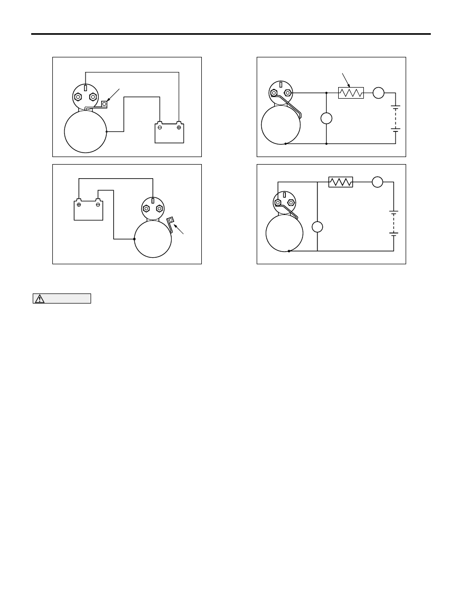
MAGNETIC SWITCH HOLD-IN TEST
AK300650 AB
<4G1>
S
B
M
Wire
Battery
Starter
motor
AKX01244
<4G6>
S
B
M
Battery
Starter
motor
Wire
AF
1. Disconnect the field coil wire from the M-terminal
of the magnetic switch.
CAUTION
This test must be performed quickly (in less than
10 seconds) to prevent the coil from burning.
2. Connect a 12-volt battery between the S-terminal
and body.
3. Manually pull out the pinion as far as the pinion
stopper position.
4. If the pinion remains out, everything is in order. If
the pinion moves in, the hold-in circuit is open.
Replace the magnetic switch.
FREE RUNNING TEST
AK300651AB
<4G1>
S
A
M
V
B
Carbon-pile rheostat
Battery
Voltmeter
Ammeter
Starter
motor
AKX01246
<4G6>
S
M
B
Ammeter
Carbon-pile
rheostat
Battery
Starter
motor
Voltmeter
AF
A
V
1. Place the starter motor in a vise equipped with
soft jaws and connect a fully-charged 12-volt
battery to the starter motor as follows:
2. Connect a test ammeter (100-ampere scale) and
carbon pile rheostat in series between the battery
(+) terminal and starter motor terminal.
3. Connect a voltmeter (15-volt scale) across the
starter motor.
4. Rotate the rheostat to full-resistance position.
5. Connect the battery cable from the battery (-)
terminal to the starter motor body.
6. Adjust the rheostat until the battery voltage shown
on the voltmeter is 11 V.
7. Confirm that the maximum amperage is within the
specifications and that the starter motor turns
smoothly and freely.
Current:
<4G1> maximum 95 Amps
<4G6> maximum 90 Amps