Mitsubishi Lancer. Manual - part 42
ADJUSTMENT OF OTHER PARTS
REFERENCE MATERIAL
8-10
REAR WHEEL ALIGNMENT
M4080010000129
Measure wheel alignment with an alignment equip-
ment on level earth.
The rear suspension, wheels, and tyres should be
serviced to the normal condition prior to wheel align-
ment measurement.
CAMBER
Standard value:
−0°40' ± 0°30' (Left/right
deviation within 30')
CAUTION
Never subject the wheel bearings to the vehicle
load when the rear wheel hub nuts (self-locking
nuts) or special tool wheel alignment gauge
attachment (MB991014) are loosened.
NOTE:
AC001079
MB991014
AG
<Vehicles with aluminium wheels>
For vehicles with aluminium wheels, attach the cam-
ber/caster/kingpin gauge to the trailing arm spindle
by using special tool wheel alignment gauge attach-
ment (MB991014). Tighten the special tool to the
same torque 175
±
25 N
⋅
m as the rear wheel hub nut
(self-locking nut).
If camber is not within the standard value, adjust by
following procedures.
1. Disconnect the conjunction of the control link and
the trailing arm.
AC006159 AC
Camber adjusting bolt
Lower arm
assembly
2. Carry out adjustment by turning the camber
adjusting bolt (lower arm assembly mounting bolt
which is located on the inner side of the body).
NOTE:
.
•
LH: Clockwise viewed from the front
→
(+)
camber
•
RH: Clockwise viewed from the front
→
(
−
)
camber
•
AC006160 AC
Connecting bolt
The scale has gradations of approximately 14'.
CAUTION
To prevent bushings from breakage, the connect-
ing bolt should be temporarily tightened, and
then fully tightened to 90
± 10 N⋅m with the vehi-
cle on the earth in the unladen condition.
3. Tighten the control link to the trailing arm.
4. After adjusting the camber, the toe should be
adjusted.
TOE-IN
Standard value:
At the centre of tyre tread: 3
± 2 mm
Toe angle (per wheel): 0
°08' ± 0°05'
If toe-in is not within the standard value, adjust by fol-
lowing procedures.
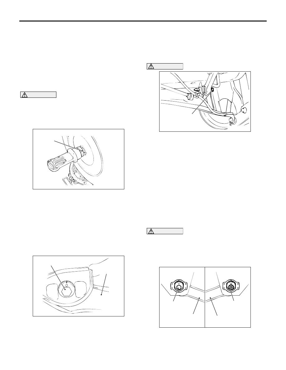
CAUTION
To prevent bushings from breakage, the control
link mounting nut should be temporarily tight-
ened, and then fully tightened to 120
± 10 N⋅m
with the vehicle on the earth in the unladen con-
dition.
AC006145 AD
Control link
Toe adjusting bolt
Control link
<Control link front view> <Control link rear view>
Control link
mounting nut
Carry out adjustment by turning the toe adjusting bolt
(control link mounting bolt which is located on the
inner side of the body).