Mitsubishi Lancer (4A9 engine). Manual - part 293
AC612706
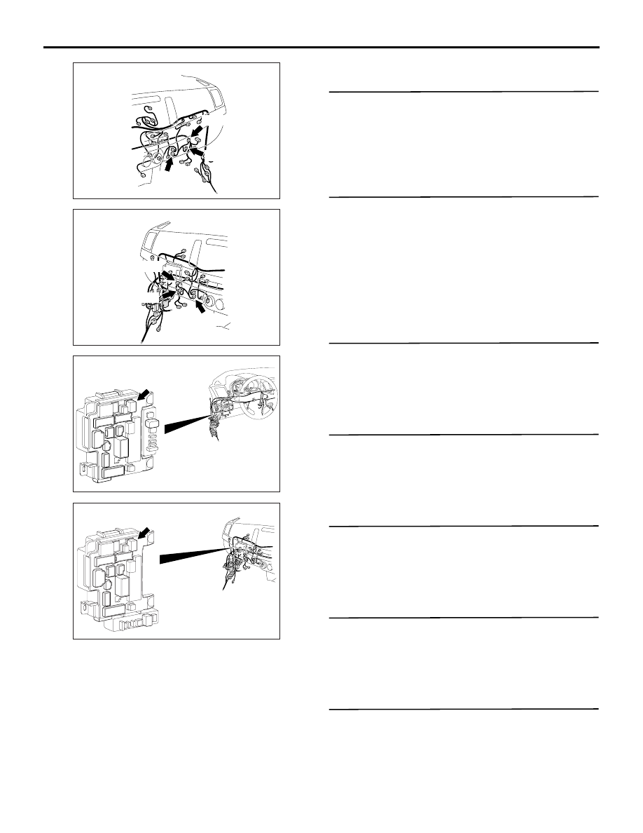
Connectors: C-15, C-109, C-110 <LHD>
AF
C-15 (B)
C-109
C-110
AC612710
Connectors: C-15, C-109, C-110 <RHD>
AT
C-15 (B)
C-109
C-110
AC612709
Connector: C-303<LHD>
AO
ETACS-ECU
AC612717
Connector: C-303 <RHD>
AO
ETACS-ECU
TROUBLESHOOTING
HEATER, AIR CONDITIONER AND VENTILATION
55A-53
COMMENTS ON TROUBLE SYMPTOM
If the blower motor does not operate, the blower
motor circuit system may be defective.
PROBABLE CAUSES
• Malfunction of the blower motor
• Malfunction of the power transistor
• Malfunction of the A/C-ECU
• Damaged wiring harness or connectors
DIAGNOSIS PROCEDURE
STEP 1. M.U.T.-III CAN bus diagnostics
Use the M.U.T.-III to diagnose the CAN bus lines.
Q: Is the check result normal?
YES :
Go to Step 2.
NO :
Repair the CAN bus lines (Refer to GROUP
54C
− Troubleshooting ).
STEP 2. M.U.T.-III diagnosis code.
Recheck if the diagnosis code is set.
(1) Erase the diagnosis code.
(2) Ignition switch: LOCK (OFF) to ON
(3) Check if the diagnosis code is set.
Q: Is the diagnosis code set?
YES :
Carry out the diagnosis code procedures.
Refer to .
NO :
Go to Step 3.
STEP 3. Connector check: C-303 blower relay
connector
Q: Is the check result normal?
YES :
Go to Step 4.
NO :
Repair the connector.
STEP 4. Check the blower relay.
Refer to .
Q: Is the blower relay in good condition?
YES :
Go to Step 5.
NO :
Replace the blower relay.
STEP 5. Connector check: C-110 blower motor
connector
Q: Is the check result normal?
YES :
Go to Step 6.
NO :
Repair the connector.
STEP 6. Check the blower motor.
Refer to .
Q: Is the check result normal?
YES :
Go to Step 7.
NO :
Replace the blower motor.
STEP 7. Voltage measurement at C-110 blower
motor connector.
(1) Disconnect the connector, and measure at the
wiring harness side.
(2) Turn the ignition switch to the ON position.
(3) Voltage between terminal 1 and body earth.