Mitsubishi Lancer (4A9 engine). Manual - part 269
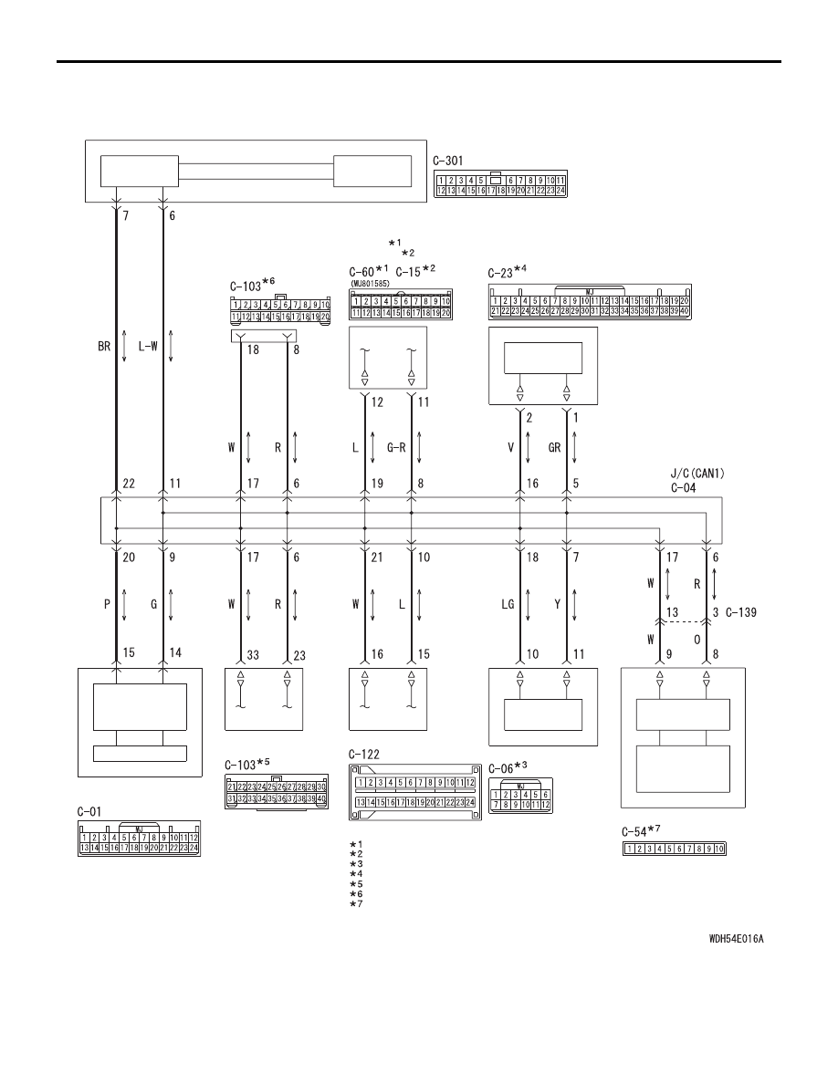
CAN-B Communication Circuit
ETACS-ECU
INTERFACE
CIRCUIT
CAN DRIVE
CIRCUIT
SRS-ECU
CPU
WCM
CAN BOX UNIT
KOS-ECU
CAN
TRANSCEIVER
CIRCUIT
CAN DRIVE
CIRCUIT
CAN DRIVE
CIRCUIT
Wire colour code
B : Black LG : Light green G : Green L : Blue W : White Y : Yellow SB : Sky blue
BR : Brown O : Orange GR : Grey R : Red P : Pink V : Violet PU : Purple SI : Silver
RADIO AND
CD PLAYER
CAN
TRANSCEIVER
CIRCUIT
INTERFACE
CIRCUIT
VEHICLES WITHOUT A/C
:
VEHICLES WITH A/C
:
VEHICLES WITH KOS
:
NOTE
VEHICLES WITH WCM
:
VEHICLES WITH RADIO AND CD PLAYER
:
VEHICLES WITHOUT AUDIO
:
VEHICLES WITH MMCS
:
COMBINATION
METER
HEATER CONTROL
PANEL
A/C-ECU
SPARE
CONNECTOR
(FOR AUDIO)
TROUBLESHOOTING
CONTROLLER AREA NETWORK (CAN)
54C-100