Mitsubishi Lancer (4A9 engine). Manual - part 266
ACB02645
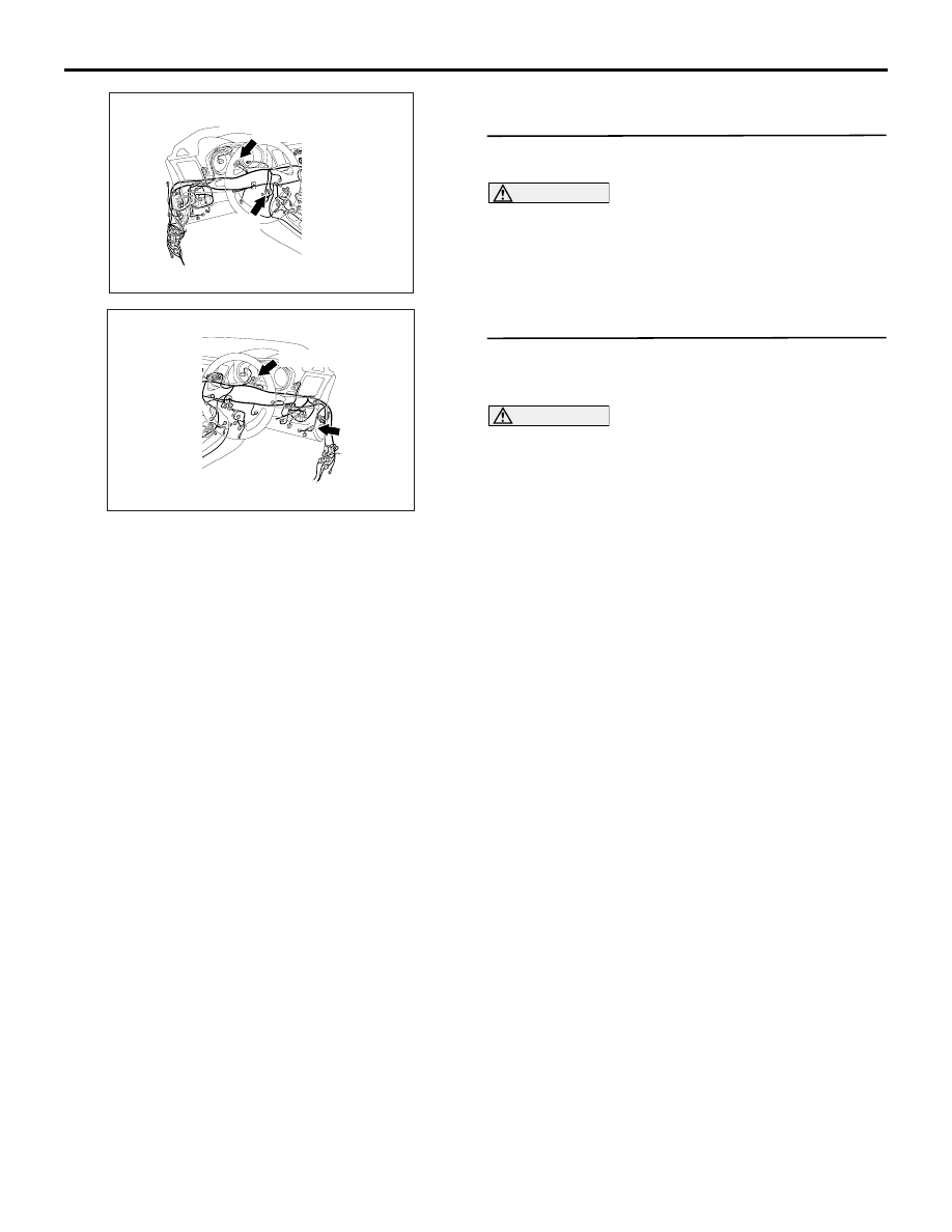
AM
C-04 (GR)
C-23
Connectors: C-04, C-23 <LHD>
ACB02647
AI
C-04 (GR)
Connectors: C-04, C-23 <RHD>
C-23
TROUBLESHOOTING
CONTROLLER AREA NETWORK (CAN)
54C-88
FUNCTION
If the M.U.T.-III cannot communicate with the KOS-
ECU, this diagnosis result will be set.
TROUBLE JUDGEMENT CONDITIONS
If a communication flag is not set for the KOS-ECU,
the ETACS-ECU determines that there is a failure.
TROUBLESHOOTING HINTS
• Malfunction of the connector [joint connector
(CAN1) or KOS-ECU connector improperly con-
nected]
• Malfunction of the wiring harness [open circuit
between the KOS-ECU connector and the joint
connector (CAN1), or power supply circuit to the
KOS-ECU]
• Malfunction of the KOS-ECU
DIAGNOSIS PROCEDURE
STEP 1. Connector check: C-04 joint connector
(CAN1) and C-23 KOS-ECU connector
CAUTION
The strand end of the twist wire should be within
10 cm from the connector. For details refer to .
Q: Is the check result normal?
YES :
Go to Step 2.
NO :
Repair the defective connector.
STEP 2. Check the wiring harness between C-23
KOS-ECU connector and C-04 joint connector
(CAN1)
CAUTION
Strictly observe the specified wiring harness
repair procedure. For details refer to .
Disconnect KOS-ECU connector and joint connector
(CAN1), and check the following wiring harness for
open circuit
(1) The wiring harness between C-23 KOS-ECU
connector terminal No.1 and C-04 joint connector
(CAN1) terminal No.5 <CAN_H>
OK: Continuity exists (2
Ω or less)
(2) The wiring harness between C-23 KOS-ECU
connector terminal No.2 and C-04 joint connector
(CAN1) terminal No.16 <CAN_L>
OK: Continuity exists (2
Ω or less)
Q: Is the check result normal?
YES :
Check the power supply circuit of the KOS-
ECU. Refer to GROUP 42B
−
Troubleshooting .
NO :
Repair the wiring harness.