Mitsubishi Lancer (4A9 engine). Manual - part 251


  Index      Mitsubishi     Mitsubishi Lancer (4A9 engine) 12GS41 & 44S - service repair manual


Search            


Content   ..  249  250  251  252   ..


Mitsubishi Lancer (4A9 engine). Manual - part 251


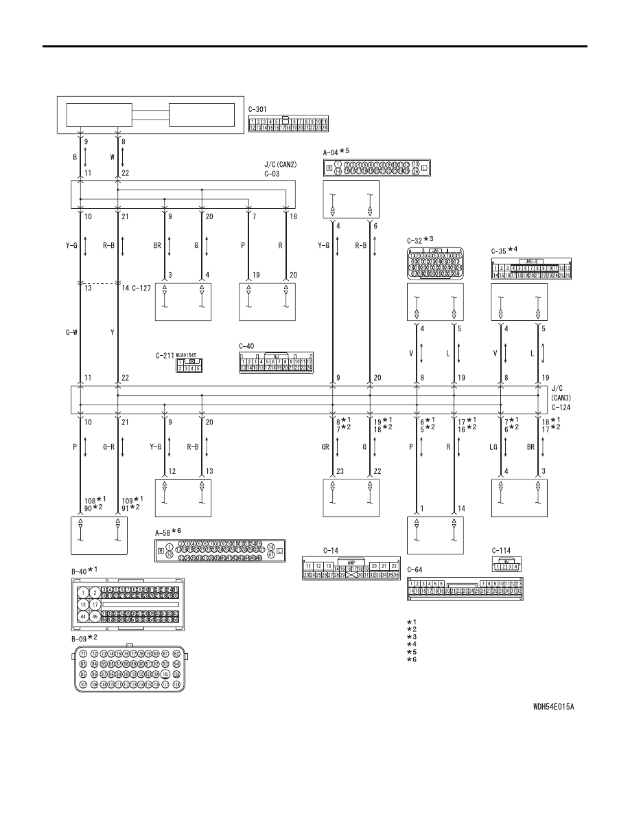
CAN-C Communication Circuit <Except for RALLIART>

ETACS-ECU

INTERFACE 
CIRCUIT

CAN DRIVE 
CIRCUIT

ASC-ECU

A/T-ECU

ABS-ECU

CVT-ECU

STEERING 
WHEEL SENSOR 
<AFS, ASC>

ENGINE-ECU

ELECTRIC 
POWER 
STEERING-ECU

Wire colour code 
B : Black     LG : Light green     G : Green     L : Blue     W : White 
Y : Yellow     SB : Sky blue     BR : Brown     O : Orange     GR : Grey 
R : Red     P : Pink     V : Violet     PU : Purple     SI : Silver

CORNER SENSOR/
BACK SENSOR-ECU

DIESEL

:

PETROL

:

1800-PETROL, 2000

:

NOTE

PETROL (EXCEPT SOHC)

:

VEHICLES WITHOUT ASC

:

VEHICLES WITH ASC

:

HEADLAMP 
AUTOMATIC 
LEVELLING-ECU

AS&G-ECU

TROUBLESHOOTING

CONTROLLER AREA NETWORK (CAN)

54C-28

AC801250

Connectors: A-04, A-58 <LHD>

AB

A-04 (B), 
A-58 (B)

AC801253

AG

Connector: A-58 <RHD>

A-58 (B)

AC800715

Connectors: B-09, B-40

BC

B-09 (GR), 
B-40 (B)

ACB02645

AE

C-03 (GR)

C-35

Connectors: C-03, C-35, C-40, C-124, C-127
<LHD>

C-40

C-127 (GR)

C-124 (GR)

ACB02648

AD

C-03 (GR)

C-114

C-35

Connectors: C-03, C-35, C-114, C-127 <RHD>

C-127 (GR)

ACB02646

AD

C-64

C-14

C-114

Connectors: C-14, C-64, C-114 <LHD>

ACB02647

AD

C-64

C-124 (GR)

C-04 (GR)

Connectors: C-14, C-64, C-124 <RHD>

AC612708 AW

Connector: C-211 <LHD>

AC612716 AX

Connectors: C-211 <RHD>

ACA00886

BE

Connector: C-301 <LHD>
ETACS-ECU

TROUBLESHOOTING

CONTROLLER AREA NETWORK (CAN)

54C-29

ACA00887

BF

Connector: C-301 <RHD>
ETACS-ECU

TROUBLESHOOTING

CONTROLLER AREA NETWORK (CAN)

54C-30

FUNCTION
If a line-to-line short is present in the CAN-C lines, 
this diagnosis result will be set.

TROUBLE JUDGEMENT CONDITIONS
If only diagnosis code U0001 is set, the ETACS-ECU 
determines that there is a failure.

TROUBLESHOOTING HINTS

• Malfunction of the connector (joint connectors or 

ECU connectors improperly connected)

• Malfunction of the wiring harness (line-to-line 

short in the CAN-C main or sub bus lines)

• Malfunction of the ECU (ECU on CAN-C lines 

failed)

DIAGNOSIS PROCEDURE

STEP 1. Connector check: C-03 joint connector 
(CAN2) and C-124 joint connector (CAN3)

CAUTION

The strand end of the twist wire should be within 
10 cm from the connector. For details refer to .

Q: Is the check result normal?

YES <vehicles with ASC or AFS> : 

Go to Step 2.

YES <vehicles without ASC and without AFS with 
reversing sensor system> : 

Go to Step 3.

YES <vehicles without ASC and without AFS 
without reversing sensor system> : 

Go to Step 4.

NO  : 

Repair the defective connector.

STEP 2. Check the wiring harness between C-211 
steering wheel sensor connector and C-03 joint 
connector (CAN2) for line-to-line short.

CAUTION

• A digital multimeter should be used. For 

details refer to .

• The test wiring harness should be used. For 

details refer to .

(1) Disconnect joint connector (CAN2), and check 

that there is continuity at the harness side.

(2) Check that there is continuity between C-03 joint 

connector terminal No.9 and 20.

OK: No continuity

Q: Is the check result normal?

YES <vehicles with reversing sensor system> : 

Go 

to Step 3.

YES <vehicles without reversing sensor system> : 

Go to Step 4.

NO : 

Go to Step 11.

STEP 3. Check the wiring harness between C-40 
Corner sensor/back sensor-ECU connector and 
C-03 joint connector (CAN2) for line-to-line short.

CAUTION

• A digital multimeter should be used. For 

details refer to .

• The test wiring harness should be used. For 

details refer to .

(1) Disconnect joint connector (CAN2), and check 

that there is continuity at the harness side.

(2) Check that there is continuity between C-03 joint 

connector terminal No.7 and 18.

OK: No continuity

Q: Is the check result normal?

YES : 

Go to Step 4.

NO : 

Go to Step 12.

STEP 4. Check the wiring harness between C-301 
ETACS-ECU connector and C-03 joint connector 
(CAN2) for line-to-line short.

CAUTION

• A digital multimeter should be used. For 

details refer to .

• The test wiring harness should be used. For 

details refer to .

(1) Disconnect joint connector (CAN2), and check 

that there is continuity at the harness side.

(2) Check that there is continuity between C-03 joint 

connector terminal No.11 and 22.

OK: No continuity

Q: Is the check result normal?

YES <vehicles with AFS> : 

Go to Step 5.

YES <vehicles without AFS> : 

Go to Step 6.

NO  : 

Go to Step 13.

TROUBLESHOOTING

CONTROLLER AREA NETWORK (CAN)

54C-31

STEP 5. Check the wiring harness between C-14 
headlamp automatic levelling-ECU connector 
and C-124 joint connector (CAN3) for line-to-line 
short.

CAUTION

• A digital multimeter should be used. For 

details refer to .

• The test wiring harness should be used. For 

details refer to .

(1) Disconnect joint connector (CAN3), and check 

that there is continuity at the harness side.

(2) Check that there is continuity between C-124 

joint connector terminal No.7 and 18 <Petrol>.

OK: No continuity

(3) Check that there is continuity between C-124 

joint connector terminal No.8 and 19 <Diesel>.

OK: No continuity

Q: Is the check result normal?

YES : 

Go to Step 6.

NO : 

Go to Step 14.

STEP 6. Check the wiring harness between A-04 
ABS-ECU connector <vehicles without ASC> or 
A-58 ASC-ECU connector <vehicles with ASC> 
and C-124 joint connector (CAN3) for line-to-line 
short.

CAUTION

• A digital multimeter should be used. For 

details refer to .

• The test wiring harness should be used. For 

details refer to .

(1) Disconnect joint connector (CAN3), and check 

that there is continuity at the harness side.

(2) Check that there is continuity between C-124 

joint connector terminal No.9 and 20.

OK: No continuity

Q: Is the check result normal?

YES <A/T or CVT> : 

Go to Step 7.

YES <M/T (vehicles with electric power steering) > : 

Go to Step 8.

YES <M/T (vehicles without electric power steering 
with automatic stop & go (AS&G) system)> : 

Go to 

Step 9.

YES <M/T (vehicles without electric power steering 
without automatic stop & go (AS&G) system)> : 

Go to Step 10.

NO  : 

Go to Step 15.

STEP 7. Check the wiring harness between C-32 
A/T-ECU connector <A/T> or C-35 CVT-ECU 
connector <CVT> and C-124 joint connector 
(CAN3) for line-to-line short.

CAUTION

• A digital multimeter should be used. For 

details refer to .

• The test wiring harness should be used. For 

details refer to .

(1) Disconnect joint connector (CAN3), and check 

that there is continuity at the harness side.

(2) Check that there is continuity between C-124 

joint connector terminal No.8 and 19.

OK: No continuity

Q: Is the check result normal?

YES <vehicles with electric power steering> : 

Go 

to Step 8.

YES <vehicles without electric power steering and 
with automatic stop & go (AS&G) system> : 

Go to 

Step 9.

YES <vehicles without electric power steering and 
without automatic stop & go (AS&G) system> : 

Go 

to Step 10.

NO  : 

Go to Step 16.

STEP 8. Check the wiring harness between C-114 
electric power steering-ECU connector and C-
124 joint connector (CAN3) for line-to-line short.

CAUTION

• A digital multimeter should be used. For 

details refer to .

• The test wiring harness should be used. For 

details refer to .

(1) Disconnect joint connector (CAN3), and check 

that there is continuity at the harness side.

(2) Check that there is continuity between C-124 

joint connector terminal No.6 and 17 <Petrol>.

OK: No continuity

(3) Check that there is continuity between C-124 

joint connector terminal No.7 and 18 <Diesel>.

OK: No continuity

Q: Is the check result normal?

YES <vehicles with automatic stop & go (AS&G) 
system> : 

Go to Step 9.

YES <vehicles without automatic stop & go (AS&G) 
system> : 

Go to Step 10.

NO  : 

Go to Step 17.


Content   ..  249  250  251  252   ..