Mitsubishi Lancer (4A9 engine). Manual - part 237
SECURITY ALARM
CHASSIS ELECTRICAL
54A-610
SECURITY ALARM SIREN REMOVAL
AND INSTALLATION
M1547005000126
Pre-removal operation
• Removal of brake booster assembly (Refer to GROUP
35A
− Master Cylinder Assembly and Brake Booster
Assembly ) <RHD>
• Removal of ABS-ECU or ASC-ECU harness connector
(Refer to GROUP 35B
− Hydraulic Unit or GROUP 35C-
Hydraulic Unit ) <LHD>
Post-installation operation
• Installation of brake booster assembly (Refer to GROUP
35A
− Master Cylinder Assembly and Brake Booster
Assembly ) <RHD>
• Installation of ABS-ECU or ASC-ECU harness connector
(Refer to GROUP 35B
− Hydraulic Unit or GROUP 35C-
Hydraulic Unit ) <LHD>
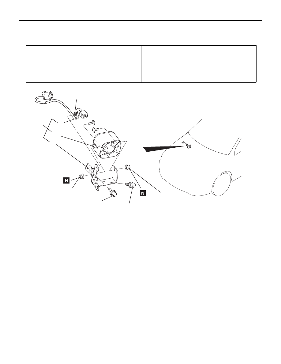
ACA00466
9.0 ± 3.0 N·m
9.0 ± 3.0 N·m
2
4
3
AC
Clip
18 ± 7 N·m <RHD>
18 ± 7 N·m <LHD>
1
Removal Steps
1.
Security alarm siren assembly
2.
Security alarm siren bracket
3.
Security alarm siren
4.
Sub harness
Removal Steps (Continued)