Mitsubishi Lancer (4A9 engine). Manual - part 234


  Index      Mitsubishi     Mitsubishi Lancer (4A9 engine) 12GS41 & 44S - service repair manual


Search            


Content   ..  232  233  234  235   ..


Mitsubishi Lancer (4A9 engine). Manual - part 234


SECURITY ALARM

CHASSIS ELECTRICAL

54A-598

COMMENTS ON TROUBLE SYMPTOM
If this function does not work normally, the input sig-
nal circuits to the components below, the security 
indicator, the ETACS-ECU or the CAN bus line may 
have a problem.

• Keyless entry transmitter

• Key reminder switch

• Ignition switch (ACC)

• Hood switch

• Door switches

• Tailgate latch switch

PROBABLE CAUSES

• Malfunction of CAN bus line

• Malfunction of security indicator

• Malfunction of keyless entry transmitter

• Malfunction of the key reminder switch

• Malfunction of door switch

• Malfunction of tailgate latch switch

• Malfunction of hood switch

• Malfunction of the KOS-ECU

• Malfunction of the WCM

• Malfunction of the ETACS-ECU

• Damaged harness wires and connectors

DIAGNOSIS PROCEDURE

STEP 1. M.U.T.-III CAN bus diagnostics
Use the M.U.T.-III to diagnose the CAN bus lines.

Q: Is the check result normal?

YES : 

Go to Step 2.

NO : 

Repair the CAN bus line. (Refer to GROUP 
54C 

− Troubleshooting ).

STEP 2. M.U.T.-III other system diagnosis code
Check if diagnosis code is set to the KOS-ECU 
<vehicles with KOS> or WCM <vehicles with WCM>.

Q: Is the diagnosis code set?

YES <vehicles with KOS> : 

Troubleshoot the KOS 

(Refer to GROUP 42B 

− KOS ).

YES <vehicles with WCM> : 

Troubleshoot the 

WCM (Refer to GROUP 42C 

− WCM ).

NO  : 

Go to Step 3.

STEP 3. Check the keyless entry transmitter.
Check that the keyless entry system works normally.

Q: Is the check result normal?

YES : 

Go to Step 4.

NO <vehicles with KOS> : 

Troubleshoot the KOS 

(Refer to GROUP 42B 

− KOS ).

NO <vehicles with WCM> : 

Troubleshoot the WCM 

(Refer to GROUP 42C 

− WCM ).

ACA00892

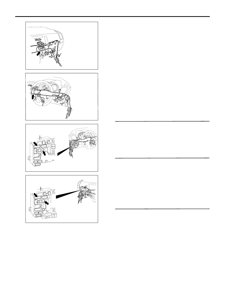
Connector: C-10 <LHD>

AC

C-10

ACA00895AD

Connector: C-10 <RHD>

ACA00886

AI

Connectors: C-307, C-317 <LHD>
ETACS-ECU

C-317

C-307 (B)

ACA00887

AI

Connectors: C-307, C-317 <RHD>
ETACS-ECU

C-317

C-307

SECURITY ALARM

CHASSIS ELECTRICAL

54A-599

STEP 4. M.U.T.-III data list
Use the ETACS-ECU service data to check the sig-
nals related to the security alarm.

• Turn the ignition switch to the ACC position.

• Turn the ignition switch to the OFF position (with 

ignition key <vehicles with WCM> or emergency 
key <vehicles with KOS> inserted).

• Open each door.

• Open the tailgate.

• Open the hood.

• Close each door.

• Close the tailgate.

• Turn the ignition switch to the ’’LOCK’’ (OFF) 

position (keep the ignition key <vehicles with 
WCM> or emergency key <vehicles with KOS> 
removed).

OK: Normal conditions are displayed for all 
the items.

Q: Is the check result normal?

YES <Normal conditions are displayed for all the 
items.> : 

Go to Step 5.

NO <Normal condition is not displayed for item No. 
256.> : 

Troubleshoot the ETACS-ECU. Refer to 

Inspection Procedure 5 "The front door 
switch (RH) signal is not received" .

NO <Normal condition is not displayed for item No. 
257.> : 

Troubleshoot the ETACS-ECU. Refer to 

Inspection Procedure 6 "The front door 
switch (LH) signal is not received" .

NO <Normal condition is not displayed for item No. 
258.> : 

Troubleshoot the ETACS-ECU. Refer to 

Inspection Procedure 7 "The rear door 
switch (RH) signal is not received" .

Normal condition is not displayed for item No. 259. 

Troubleshoot the ETACS-ECU. Refer to 
Inspection Procedure 8 "The rear door 
switch (LH) signal is not received" .

NO <Normal condition is not displayed for item No. 
260.> : 

Troubleshoot the ETACS-ECU. Refer to 

Inspection Procedure 9 "The trunk lid latch 
switch signal is not received"  <LANCER> 
or "The tailgate switch signal is not 
received"  <LANCER SPORTBACK>.

NO <Normal condition is not displayed for item No. 
264.> : 

Refer to Inspection Procedure 3 "Key 

reminder switch signal is not received" .

NO <Normal condition is not displayed for item No. 
266.> : 

Refer to Inspection Procedure 12 "The 

hood switch signal is not received" .

NO <Normal condition is not displayed for item No. 
288.> : 

Troubleshoot the ETACS-ECU. Refer to 

Inspection Procedure 1 "The ignition switch 
(ACC) signal is not received" .

STEP 5. Connector check: C-10 centre panel unit

Q: Is the check result normal?

YES : 

Go to Step 6.

NO : 

Repair the defective connector.

STEP 6. Security indicator check
Check that the security indicator is normal. Refer to .

Q: Is the check result normal?

Item No.

Item name

Normal 
condition

Item 256

Dr door ajar switch

Open

Item 257

As door ajar switch

Open

Item 258

RR door ajar switch

Open

Item 259

RL door ajar switch

Open

Item 260

Trunk/gate trunk ajar 
switch

Open

Item 264

Handle lock switch

Key in

Item 266

Hood switch

ON

Item 288

ACC switch

ON

Item No.

Item name

Normal 
condition

Item 256

Dr door ajar switch

Close

Item 257

As door ajar switch

Close

Item 258

RR door ajar switch

Close

Item 259

RL door ajar switch

Close

Item 260

Trunk/gate trunk ajar 
switch

Close

Item No.

Item name

Normal 
condition

Item 264

Handle lock switch

Key out

Item 288

ACC switch

OFF

AC609727AB

SECURITY ALARM

CHASSIS ELECTRICAL

54A-600

YES : 

Go to Step 7.

NO : 

Replace the centre panel unit.

STEP 7. Connector check: C-307 ETACS-ECU 
connector

Q: Is the check result normal?

YES : 

Go to Step 8.

NO : 

Repair the defective connector.

STEP 8. Voltage measurement at the C-307 
ETACS-ECU connector.
(1) Disconnect the connector, and measure at the 

wiring harness side.

(2) Measure the voltage between the C-307 ETACS-

ECU connector terminal No. 2 and the body 
earth.

OK: System voltage

Q: Is the check result normal?

YES : 

Go to Step 10.

NO : 

Go to Step 9.

STEP 9. Wiring harness check between the C-307 
ETACS-ECU connector terminal No. 2 and the 
fusible link (36) <PETROL> or (38) <DIESEL>

• Check the power supply line for open circuit.

Q: Is the check result normal?

YES : 

The trouble can be an intermittent 

malfunction (Refer to GROUP 00 

− How to 

use Troubleshooting/inspection Service 
Points 

− How to Cope with Intermittent 

Malfunction ).

NO : 

Repair the wiring harness.

STEP 10. Connector check: C-317 ETACS-ECU 
connector

Q: Is the check result normal?

YES : 

Go to Step 11.

NO : 

Repair the defective connector.

STEP 11. Wiring harness check between the C-
317 ETACS-ECU connector terminal No. 2, 9 and 
the C-10 centre panel unit connector terminal No. 
15, 12

• Check the input/output lines for open circuit and 

short circuit.

Q: Is the check result normal?

YES : 

Go to Step 12.

NO : 

Repair the wiring harness.

STEP 12. Retest the system

Q: Does the security alarm work normally?

YES : 

The trouble can be an intermittent 

malfunction (Refer to GROUP 00 

− How to 

use Troubleshooting/inspection Service 
Points 

− How to Cope with Intermittent 

Malfunction ).

NO : 

Replace the ETACS-ECU.

Inspection Procedure 2: The interior alarm does not work normally while the security alarm is 
triggered.

CAUTION

Before replacing the ECU, ensure that the power supply circuit, the earth circuit and the communica-
tion circuit are normal.
COMMENTS ON TROUBLE SYMPTOM
If the interior alarm does not work normally, ETACS-
ECU, or combination meter built-in buzzer may have 
a problem.

PROBABLE CAUSES

• Malfunction of the ETACS-ECU

• Malfunction of combination meter

• Damaged harness wires and connectors

DIAGNOSIS PROCEDURE

STEP 1. M.U.T.-III CAN bus diagnostics
Use the M.U.T.-III to diagnose the CAN bus lines.

Q: Is the check result normal?

YES : 

Go to Step 2.

NO : 

Repair the CAN bus line (Refer to GROUP 
54C 

− Troubleshooting ).

SECURITY ALARM

CHASSIS ELECTRICAL

54A-601

STEP 2. M.U.T.-III diagnosis code
Check if diagnosis code is set to the ETACS-ECU.

Q: Is the diagnosis code set?

YES : 

Troubleshoot the ETACS-ECU. Refer to .

NO : 

Go to Step 3.

STEP 3. M.U.T.-III actuator test
Perform the combination meter actuator test, and 
check that the buzzer sounds normally.

• Item 12: Buzzer

Q: Is the check result normal?

YES : 

Go to Step 4.

NO : 

Replace the combination meter.

STEP 4. Retest the system
Check that the security alarm works normally.

Q: Is the check result normal?

YES : 

The trouble can be an intermittent 

malfunction (Refer to GROUP 00 

− How to 

use Troubleshooting/inspection Service 
Points 

− How to Cope with Intermittent 

Malfunction ).

NO : 

Replace the ETACS-ECU.

Inspection Procedure 3: The hazard warning lamps do not flash while the security alarm is triggered.

CAUTION

Before replacing the ECU, ensure that the power supply circuit, the earth circuit and the communica-
tion circuit are normal.
COMMENTS ON TROUBLE SYMPTOM
If the hazard warning lamps do not flash normally, 
the ETACS-ECU may be defective.

PROBABLE CAUSES

• Malfunction of the ETACS-ECU

• Damaged harness wires and connectors

DIAGNOSIS PROCEDURE

STEP 1. Check that the hazard warning lamps 
operate.
Check that the hazard warning lamps illuminate nor-
mally.

Q: Is the check result normal?

YES : 

Go to Step 2.

NO : 

Troubleshoot the hazard warning lamps. 
Refer to Inspection Procedure 1 "The 
hazard warning lamps do not illuminate" .

STEP 2. M.U.T.-III diagnosis code
Check if diagnosis code is set to the ETACS-ECU.

Q: Is the diagnosis code set?

YES : 

Troubleshoot the ETACS-ECU. Refer to .

NO : 

Go to Step 3.

STEP 3. Retest the system
Check that the security alarm works normally.

Q: Is the check result normal?

YES : 

The trouble can be an intermittent 

malfunction (Refer to GROUP 00 

− How to 

use Troubleshooting/inspection Service 
Points 

− How to Cope with Intermittent 

Malfunction ).

NO : 

Replace the ETACS-ECU.


Content   ..  232  233  234  235   ..