Mitsubishi Lancer (4A9 engine). Manual - part 200


  Index      Mitsubishi     Mitsubishi Lancer (4A9 engine) 12GS41 & 44S - service repair manual


Search            


Content   ..  198  199  200  201   ..


Mitsubishi Lancer (4A9 engine). Manual - part 200


HANDS FREE ECU

CHASSIS ELECTRICAL

54A-462

STEP 3. Check the USB adapter.
Check that the continuity exists between the front 
side terminals of USB adapter and rear side termi-
nals of USB adapter. (Refer to )

Q: Is the check result normal?

YES : 

Go to Step 4.

NO : 

Replace the USB adapter.

STEP 4. Check the USB cable.
Check that the USB cable is connected to the USB 
adapter or hands free ECU normally. Or check the 
USB cable for damage such as bend.

Q: Is the check result normal?

YES : 

Go to Step 5.

NO : 

Replace or repair the USB cable.

STEP 5. Connector check: C-41 hands free ECU 
connector, C-105 radio and CD player connector

Q: Is the check result normal?

YES : 

Go to Step 6.

NO : 

Repair the defective connector.

STEP 6. Check the wiring harness between C-41 
hands free ECU connector terminal No.22, 8 and 
C-105 radio and CD player connector terminal 
No. 3, 12.

• Check the signal lines for open circuit and short 

circuit.

Q: Is the check result normal?

YES : 

Go to Step 7.

NO : 

Repair the wiring harness.

STEP 7. Replace the hands free ECU temporarily, 
and check the trouble symptom.
Replace the hands free ECU temporarily, and check 
that the sound is output from the speaker.

Q: Is the check result normal?

YES : 

Replace the hands free ECU.

NO : 

Replace the radio and CD player.

Inspection Procedure 2: The USB adapter data cannot be replayed. <Vehicles with MMCS>

CAUTION

Before replacing the hands free ECU, ensure that the power supply circuit, the earth circuit and the 
communication circuit are normal.

COMMENTS ON TROUBLE SYMPTOM
If the sound replay is impossible with the USB/i Pod 
mode, the USB adapter, USB cable, hands free 
ECU, or multivision display may be defective, or a 
communication error between the multivision display 
and hands free ECU may have occurred.
NOTE: Before troubleshooting, check that the music 
file (the customer tried to replay) can be replayed. 

PROBABLE CAUSES

• The multivision display may be defective.

• The hands free ECU may be defective.

• The USB adapter may be defective.

• The USB cable may be defective.

ACA00892

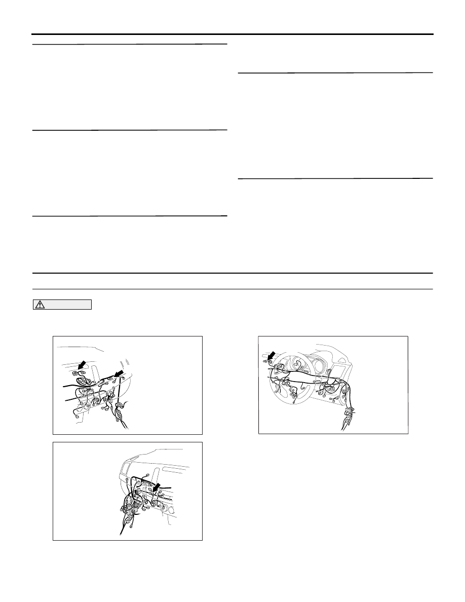
Connectors: C-41, C-142 <LHD>

AM

C-41

C-142 (GR)

ACA00896

AD

Connector: C-41 <RHD>

ACA00895AN

Connector: C-142 <RHD>

C-142 (GR)

HANDS FREE ECU

CHASSIS ELECTRICAL

54A-463

• Damaged harness wires and connectors

DIAGNOSIS PROCEDURE

STEP 1. Check the multivision display operation.
Check if the multivision display work normally and 
the sound is output.

Q: Is the check result normal?

YES : 

Go to Step 2.

NO : 

Troubleshoot the MMCS (Refer to .).

STEP 2. Check the multivision display operation.
Display the INFOR screen, and check that the 
"Mobile Phone" item is displayed.

Q: Is the check result normal?

YES : 

Go to Step 3.

NO : 

Perform Inspection Procedure 6: 
"DIAGNOSIS MODE cannot be made an 
entry. Mobile Phone item is not displayed on 
the INFOR screen of MMCS." (Refer to .)

STEP 3. Check the USB adapter.
Check that the continuity exists between the front 
side terminals of USB adapter and rear side termi-
nals of USB adapter. (Refer to )

Q: Is the check result normal?

YES : 

Go to Step 4.

NO : 

Replace the USB adapter.

STEP 4. Check the USB cable.
Check that the USB cable is connected to the USB 
adapter or hands free ECU normally. Or check the 
USB cable for damage such as bend.

Q: Is the check result normal?

YES : 

Go to Step 5.

NO : 

Replace or repair the USB cable.

STEP 5. Connector check: C-41 hands free ECU 
connector, C-142 and multivision display 
connector

Q: Is the check result normal?

YES : 

Go to Step 6.

NO : 

Repair the defective connector.

STEP 6. Check the wiring harness between C-41 
hands free ECU connector terminal No.22, 8 and 
C-142 multivision display connector terminal No. 
45, 61.

• Check the signal lines for open circuit and short 

circuit.

NOTE: Prior to the wiring harness inspection, check 
intermediate connector C-140, and repair if neces-
sary.

Q: Is the check result normal?

YES : 

Go to Step 7.

NO : 

Repair the wiring harness.

STEP 7. Replace the hands free ECU temporarily, 
and check the trouble symptom.
Replace the hands free ECU temporarily, and check 
that the sound is output from the speaker.

Q: Is the check result normal?

YES : 

Replace the hands free ECU.

NO : 

Replace the multivision display.

HANDS FREE ECU

CHASSIS ELECTRICAL

54A-464

Inspection Procedure 3: When the speech switch is pressed, the voice information is output, but the 
voice recognition is not performed.

CAUTION

Before replacing the hands free ECU, ensure that the power supply circuit, the earth circuit and the 
communication circuit are normal.

COMMENTS ON TROUBLE SYMPTOM
When the speech switch is pushed, if the voice infor-
mation is sent but voice recognition is not executed, 
the microphone unit, hands free ECU or the commu-
nication between the microphone unit and hands free 
ECU may have a problem.

PROBABLE CAUSES

• The hands free ECU may be defective.

• The microphone unit may be defective.

• Damaged harness wires and connectors

DIAGNOSIS PROCEDURE

STEP 1. Check the diagnosis mode
Check if the microphone check result "MIC OK" is 
displayed on the diagnosis mode of hands free 
ECU.(Refer to  <vehicles with radio and CD player> 
or  <vehicles with MMCS>.)

Q: Is the check result normal?

YES : 

Go to Step 4.

NO : 

Go to Step 2.

STEP 2. Connector check: D-04 microphone unit 
connector, C-41 hands free ECU connector

Q: Is the check result normal?

YES : 

Go to Step 3.

NO : 

Repair the defective connector.

STEP 3. Check the wiring harness between C-41 
hands free ECU connector terminal No.14, 28 and 
D-04 microphone unit connector terminal No.2, 1.

• Check the signal lines for open circuit and short 

circuit.

NOTE: Prior to the wiring harness inspection, check 
intermediate connectors C-130 and repair if neces-
sary.

Q: Is the check result normal?

YES : 

Go to Step 4.

NO : 

Repair the wiring harness.

STEP 4. Replace the microphone unit 
temporarily, and check the trouble symptom.

Q: Is the check result normal?

YES : 

Replace the microphone unit.

NO : 

Go to Step 5.

STEP 5. Replace the hands free ECU temporarily, 
and check the trouble symptom.

Q: Is the check result normal?

AC612722

BL

Connector: D-04

ACA00892

Connectors: C-41 <LHD>

AN

C-41

ACA00896

AD

Connector: C-41 <RHD>

HANDS FREE ECU

CHASSIS ELECTRICAL

54A-465

YES : 

Replace the hands free ECU.

NO : 

The trouble can be an intermittent 
malfunction (Refer to GROUP 00, How to 
use Troubleshooting/inspection Service 
Points, How to Cope with Intermittent 
Malfunction ).


Content   ..  198  199  200  201   ..