Mitsubishi Lancer (4A9 engine). Manual - part 194
USB BOX
CHASSIS ELECTRICAL
54A-438
USB BOX
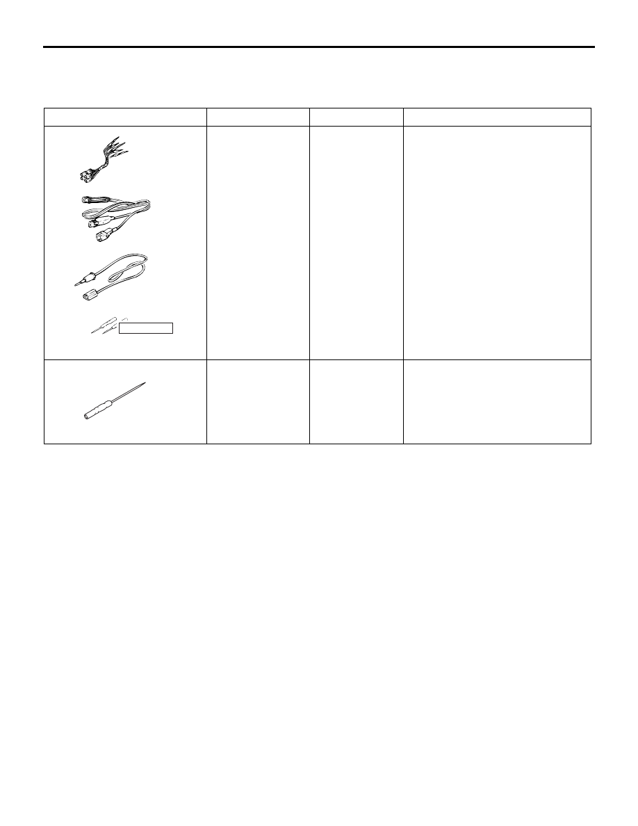
SPECIAL TOOLS
M1549100300062
TROUBLESHOOTING
STANDARD FLOW OF DIAGNOSTIC TROUBLESHOOTING
M1549100400069
Refer to GROUP 00
− Contents of troubleshooting .
DIAGNOSIS MODE <VEHICLES WITH RADIO AND CD PLAYER>
M1549101600044
Enter the diagnosis mode according to the following
steps:
1. Turn the Ignition switch to the "ACC" or "ON"
position and switch off the radio and CD player.
Tool
Number
Name
Use
MB991223
a. MB991219
b. MB991220
c. MB991221
d. MB991222
Harness set
a. Check
harness
b. LED harness
c. LED harness
adapter
d. Probe
Continuity check and voltage
measurement at harness wire or
connector
a. For checking connector pin
contact pressure
b. For checking power supply
circuit
c. For checking power supply
circuit
d. For connecting a locally sourced
tester
MB992006
Extra fine probe
Continuity check and voltage
measurement at harness wire or
connector
MB991223
a
d
c
b
DO NOT USE
BA
MB992006