Mitsubishi Lancer (4A9 engine). Manual - part 178


  Index      Mitsubishi     Mitsubishi Lancer (4A9 engine) 12GS41 & 44S - service repair manual


Search            


Content   ..  176  177  178  179   ..


Mitsubishi Lancer (4A9 engine). Manual - part 178


MITSUBISHI MULTI COMMUNICATION SYSTEM (MMCS)

CHASSIS ELECTRICAL

54A-374

NOTE: 

.

If the multivision display is reset or sound jump 
occurs at the auto restart by Auto Stop & Go 
(AS&G) System, carry out the DC/DC converter 
troubleshooting of "Audio equipment reset or 
sound jump occurs at auto start". (Refer to .) 
<Vehicles with Auto Stop & Go (AS&G) System>

For the troubleshooting of the USB box, refer to 
.<Vehicles with USB box>

For the troubleshooting of the hands free ECU, 
refer to .<Vehicles with hands free ECU>

For the troubleshooting of the steering wheel 
audio remote control switch, refer to .<Vehicles 
with steering wheel audio remote control switch>

SYMPTOM PROCEDURES

Inspection Procedure 1: No navigation screen is displayed. <Vehicles without Auto Stop & Go (AS&G) 
System>

CAUTION

Before replacing the multivision display, ensure that the power supply circuit, the earth circuit, and 
the communication circuit are normal. (Check that the voltage is 10 V or more.)

COMMENTS ON TROUBLE SYMPTOM
When the ignition switch is turned to the ACC or ON 
position, if the screen is not displayed at all, the 
power supply circuit or multivision display may have 
a problem.

PROBABLE CAUSES

• Malfunction of power supply circuit

• Malfunction of multivision display

AC701094

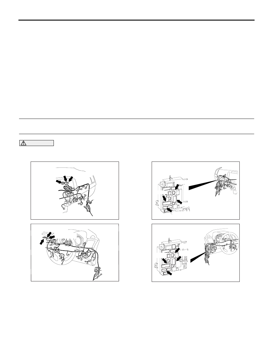
Connectors: C-142, C-143, C-144 <LHD>

BH

C-143 (GR) C-144 (GR)

C-142

AC701122 DB

Connectors: C-142, C-143, C-144 <RHD>

C-143 (GR)

C-144 (GR)

C-142

ACA00887

AT

Connectors: C-307, C-309, C-311, C-313
 <RHD> 

C-309 (B)

C-307 (B)

ETACS-ECU

C-313 (BR)

C-311

ACA00886

AT

Connectors: C-307, C-309, C-311, C-313
 <LHD>

ETACS-ECU

C-311

C-313 (BR)

C-307 (B)

C-309 (B)

MITSUBISHI MULTI COMMUNICATION SYSTEM (MMCS)

CHASSIS ELECTRICAL

54A-375

DIAGNOSIS PROCEDURE

STEP 1. M.U.T.-III other system data list
Check the input signal of ACC relay.

• Turn the ignition switch to the ACC position.

OK: Normal condition is displayed.

Q: Is the check result normal?

YES : 

Go to Step 2.

NO : 

Refer to ETACS 

− Input Signal Procedure 1 

"The ignition switch (ACC) signal is not sent 
to the ETACS-ECU" .

STEP 2. Connector check: C-144 multivision 
display and C-313 ETACS-ECU connector

Q: Is the check result normal?

YES : 

Go to Step 3.

NO : 

Repair the defective connector.

STEP 3. Voltage measurement at C-144 
multivision display connector.
(1) Disconnect the connector, and measure at the 

wiring harness-side connector.

(2) Turn the ignition switch to the ACC position.
(3) Voltage between C-144 multivision display 

connector terminal No.14 and the body earth

OK: System voltage

Q: Is the check result normal?

YES : 

Go to Step 5.

NO : 

Go to Step 4.

STEP 4. Check the wiring harness between C-144 
multivision display connector terminal No.14 and 
C-313 ETACS-ECU connector terminal No.1

• Check the power supply lines (battery power sup-

ply) for open circuit and short circuit.

NOTE: Prior to the wiring harness inspection, check 
intermediate connector C-139, C-128 and C-31, and 
repair if necessary.

Q: Is the check result normal?

YES : 

The trouble can be an intermittent 

malfunction (Refer to GROUP 00 

− How to 

use Troubleshooting/inspection Service 
Points 

− How to Cope with Intermittent 

Malfunction ).

NO : 

Repair the wiring harness.

STEP 5. Connector check: C-142, C-143, C-144 
multivision display connector

Q: Is the check result normal?

YES : 

Go to Step 6.

NO : 

Repair or replace the damaged 
component(s).

STEP 6. Resistance measurement at C-142, C-
143, C-144 multivision display connector.
(1) Disconnect C-144 multivision display connector, 

and measure the resistance available at the 
wiring harness side of the connector.

(2) Check the continuity between terminal No.9 and 

body earth.

OK: Continuity exists (2 

 or less)

(3) Disconnect C-143 multivision display connector, 

and measure the resistance available at the 
wiring harness side of the connector.

(4) Check the continuity between terminal No.25 and 

body earth.

OK: Continuity exists (2 

 or less)

(5) Disconnect C-142 multivision display connector, 

and measure the resistance available at the 
wiring harness side of the connector.

(6) Check the continuity between terminal No. 65 

and body earth.

OK: Continuity exists (2 

 or less)

Q: Is the check result normal?

YES : 

Go to Step 8.

NO : 

Go to Step 7.

STEP 7. Check the wiring harness between C-144 
multivision display connector terminal No.9 or C-
143 multivision display connector terminal No.25 
or C-142 multivision display connector terminal 
No.65 and body earth.
NOTE: Prior to the wiring harness inspection, check 
intermediate connector C-133 and C-139, and repair 
if necessary.

• Check the earth wires for open circuit.

Q: Is the check result normal?

YES : 

The trouble can be an intermittent 

malfunction (Refer to GROUP 00 

− How to 

use Troubleshooting/inspection Service 
Points 

− How to Cope with Intermittent 

Malfunction ).

NO : 

Repair the wiring harness. 

Item No.

Item name

Normal 
condition

Item 288

ACC switch

ON

MITSUBISHI MULTI COMMUNICATION SYSTEM (MMCS)

CHASSIS ELECTRICAL

54A-376

STEP 8. Voltage measurement at C-144 
multivision display connector.
(1) Disconnect the connector, and measure at the 

wiring harness-side connector.

(2) Voltage between C-144 multivision display 

connector terminal No.17 and the body earth

OK: System voltage

Q: Is the check result normal?

YES : 

Go to Step 10.

NO : 

Go to Step 9.

STEP 9. Check the wiring harness between C-144 
multivision display connector terminal No.17 and 
fusible link (38) <Diesel> or (36) <Petrol>

• Check the power supply lines (battery supply) for 

open circuit and short circuit.

NOTE: Prior to the wiring harness inspection, check 
intermediate connector C-139, C-128 and C-31, 
ETACS-ECU connector C-311 and 307, and repair if 
necessary.

Q: Is the check result normal?

YES : 

The trouble can be an intermittent 

malfunction (Refer to GROUP 00 

− How to 

use Troubleshooting/inspection Service 
Points 

− How to Cope with Intermittent 

Malfunction ).

NO : 

Repair the wiring harness.

STEP 10. Voltage measurement at C-143 
multivision display connector.
(1) Disconnect the connector, and measure at the 

wiring harness-side connector.

(2) Voltage between C-143 multivision display 

connector terminal No.21 and the body earth

OK: System voltage

Q: Is the check result normal?

YES : 

Go to Step 13.

NO : 

Go to Step 11.

STEP 11. Connector check: C-128 intermediate 
connector

Q: Is the check result normal?

YES : 

Go to Step 12.

NO : 

Repair or replace the damaged 
component(s).

STEP 12. Check the wiring harness between C-
143 multivision display connector terminal No. 21 
and C-128 intermediate connector terminal No.9

• Check the power supply lines (battery supply) for 

open circuit and short circuit.

NOTE: Prior to the wiring harness inspection, check 
intermediate connector C-133, and repair if neces-
sary.

Q: Is the check result normal?

YES : 

The trouble can be an intermittent 

malfunction (Refer to GROUP 00 

− How to 

use Troubleshooting/inspection Service 
Points 

− How to Cope with Intermittent 

Malfunction ).

NO : 

Repair the wiring harness.

STEP 13. Retest the system
Check if the multivision display power is turned ON.

Q: Is the check result normal?

YES : 

The trouble can be an intermittent 

malfunction (Refer to GROUP 00 

− How to 

use Troubleshooting/inspection Service 
Points 

− How to Cope with Intermittent 

Malfunction ).

NO : 

Replace the multivision display.

MITSUBISHI MULTI COMMUNICATION SYSTEM (MMCS)

CHASSIS ELECTRICAL

54A-377

Inspection Procedure 1: No navigation screen is displayed. <Vehicles with Auto Stop & Go (AS&G) 
System>

CAUTION

Before replacing the multivision display, ensure that the power supply circuit, the earth circuit, and 
the communication circuit are normal. (Check that the voltage is 10 V or more.)

COMMENTS ON TROUBLE SYMPTOM
When the ignition switch is turned to the ACC or ON 
position, if the screen is not displayed at all, the 
power supply circuit, DC/DC converter or multivision 
display may have a problem.

PROBABLE CAUSES

• Malfunction of DC/DC converter

• Malfunction of power supply circuit

• Malfunction of multivision display

DIAGNOSIS PROCEDURE

STEP 1. M.U.T.-III other system data list
Check the input signal of ACC relay.

• Turn the ignition switch to the ACC position.

OK: Normal condition is displayed.

Q: Is the check result normal?

YES : 

Go to Step 2.

NO : 

Refer to ETACS 

− Input Signal Procedure 1 

"The ignition switch (ACC) signal is not sent 
to the ETACS-ECU" .

STEP 2. Connector check: C-144 multivision 
display and C-313 ETACS-ECU connector

Q: Is the check result normal?

YES : 

Go to Step 3.

NO : 

Repair the defective connector.

STEP 3. Voltage measurement at C-144 
multivision display connector.
(1) Disconnect the connector, and measure at the 

wiring harness-side connector.

(2) Turn the ignition switch to the ACC position.
(3) Voltage between C-144 multivision display 

connector terminal No.14 and the body earth

OK: System voltage

Q: Is the check result normal?

YES : 

Go to Step 7.

NO : 

Go to Step 4.

ACA00892

Connectors: C-65, C-142, C-143, C-144 <LHD>

AR

C-65 (GR)

C-144 (GR)

C-143 (GR)

C-142 (GR)

ACA00895AH

Connector: C-65, C-142, C-143, C-144 <RHD>

C-65 (GR)

C-143 (GR)

C-144 (GR)

C-142 (GR)

ACA00887

AT

Connectors: C-307, C-309, C-311, C-313
 <RHD> 

C-309 (B)

C-307 (B)

ETACS-ECU

C-313 (BR)

C-311

ACA00886

AT

Connectors: C-307, C-309, C-311, C-313
 <LHD>

ETACS-ECU

C-311

C-313 (BR)

C-307 (B)

C-309 (B)

Item No.

Item name

Normal 
condition

Item 288

ACC switch

ON


Content   ..  176  177  178  179   ..