Mitsubishi Lancer (4A9 engine). Manual - part 162


  Index      Mitsubishi     Mitsubishi Lancer (4A9 engine) 12GS41 & 44S - service repair manual


Search            


Content   ..  160  161  162  163   ..


Mitsubishi Lancer (4A9 engine). Manual - part 162


RADIO AND CD PLAYER

CHASSIS ELECTRICAL

54A-310

Inspection Procedure 2: No sound is heard. <Vehicles without audio amplifier>

CAUTION

Before replacing the radio and CD player, ensure that the power supply circuit, the earth circuit and 
the communication circuit are normal.

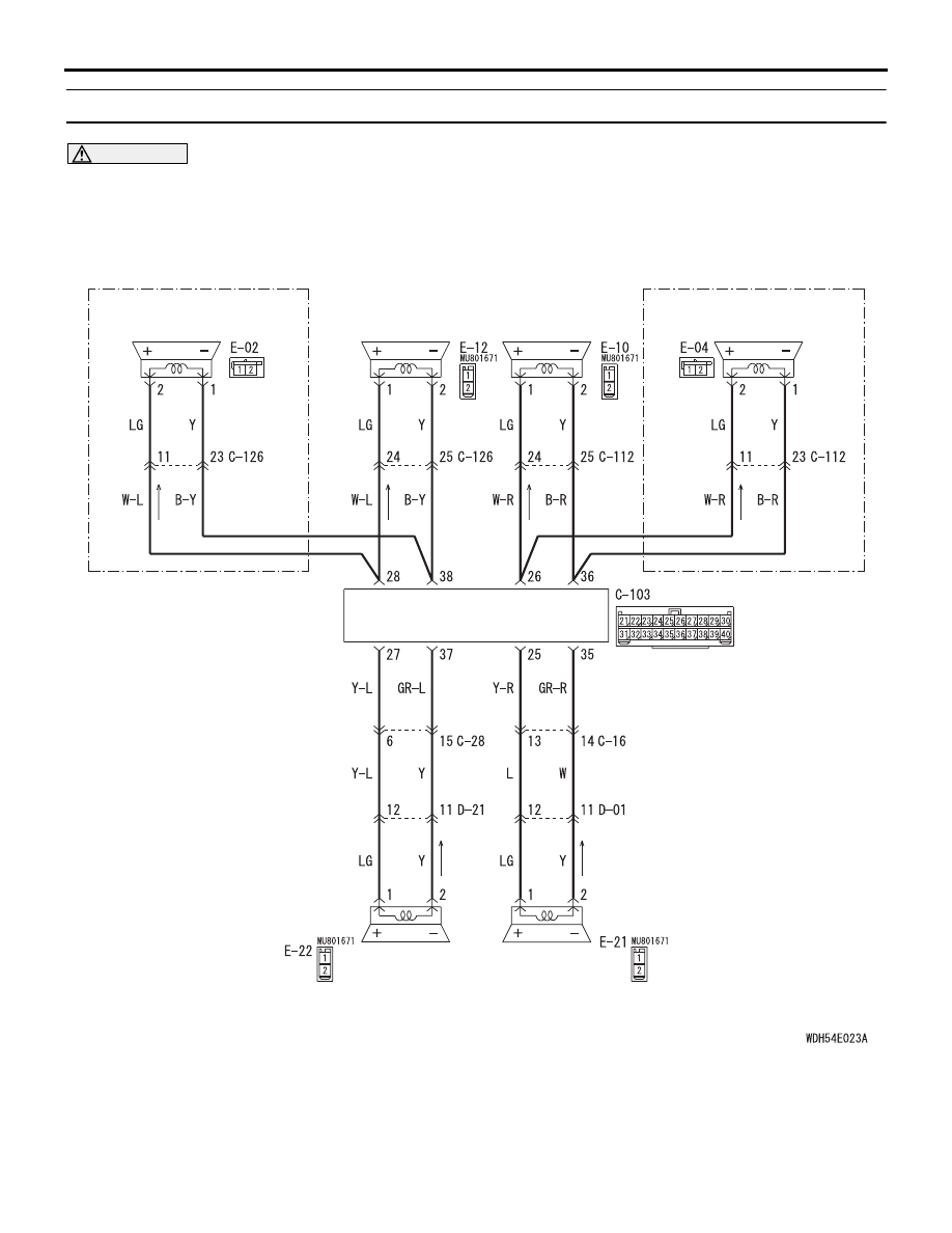
Speaker System Circuit

TWEETER (RH)

REAR DOOR 
SPEAKER (LH)

REAR DOOR 
SPEAKER (RH)

FRONT DOOR 
SPEAKER (RH)

FRONT DOOR 
SPEAKER (LH)

TWEETER (LH)

Wire colour code 
B : Black     LG : Light green     G : Green     L : Blue     W : White     Y : Yellow     SB : Sky blue 
BR : Brown     O : Orange     GR : Grey     R : Red     P : Pink     V : Violet     PU : Purple     SI : Silver

<VEHICLES WITH 6 SPEAKER>

<VEHICLES WITH 6 SPEAKER>

RADIO AND CD PLAYER

RADIO AND CD PLAYER

CHASSIS ELECTRICAL

54A-311

COMMENTS ON TROUBLE SYMPTOM
If the audio sound is not output, the radio and CD 
player may have a problem. In addition, if any of the 
speakers is short-circuited, the protection circuit 
inside the radio and CD player disables all the 
speakers to sound. Therefore, if all the speakers do 
not output sound, the speaker circuit may be shorted 
or the speaker may be defective. Also, the option 
coding information may be inconsistent.

PROBABLE CAUSES

• Malfunctions of radio and CD player

• Malfunction of speaker or tweeter

• Option coding information inconsistency

• Damaged harness wires and connectors

DIAGNOSIS PROCEDURE

STEP 1. ETACS-ECU coding data check
(1) Operate the M.U.T.-III to read the ETACS-ECU 

option coding information (Refer to GROUP 00 

− 

Coding List ).

(2) Check that the result matches with the number of 

speakers ("6 speakers" or "4 speakers") specified 
by "Number of speaker."

Q: Is the check result normal?

YES : 

Go to Step 2.

NO : 

Operate the M.U.T.-III to set the option 
coding "Number of speaker" to "6 speakers" 
or "4 speakers", and check the trouble 
symptom.

AC701094

Connector: C-103 <LHD>

AJ

AC701122 DC

Connectors: C-103 <RHD>

AC612730

Connectors: E-02, E-12

AD

E-02 (B)

E-12

AC612731

Connectors: E-04, E-10

AD

E-04 (B)

E-10

AC612733

Connector: E-21

AB

AC612732

Connector: E-22

AB

RADIO AND CD PLAYER

CHASSIS ELECTRICAL

54A-312

STEP 2. Check the following connectors.
Check the following connectors:

• E-12 front door speaker (LH) connector

• E-10 front door speaker (RH) connector

• E-22 rear door speaker (LH) connector

• E-21 rear door speaker (RH) connector

• E-02 tweeter (LH) connector <vehicles with 6-

speaker>

• E-04 tweeter (RH) connector <vehicles with 6-

speaker>

Q: Are all the connectors in good condition?

YES : 

Go to Step 3.

NO : 

Repair the defective connector.

STEP 3. Check the speaker or tweeter.
(1) Remove the speaker or tweeter. Refer to .
(2) Check that the speaker or tweeter outputs the 

noise when the voltage of 5 V is applied to the 
speaker or tweeter connector terminal.

Q: Do the speaker or tweeter output the noise?

YES : 

Go to Step 4.

NO : 

Replace the speaker or tweeter.

STEP 4. Connector check: C-103 radio and CD 
player connector

Q: Is the check result normal?

YES : 

Go to Step 5.

NO : 

Repair the defective connector.

STEP 5. Check the wiring harness between the 
speaker or tweeter connector terminal and the 
radio and CD player connector terminal.
Check the communication lines for short circuit.

• <Front door speaker (LH), tweeter (LH)> Check 

the wiring harness between E-12 front door 
speaker (LH) connector terminal No.1, 2 or E-02 
tweeter (LH) connector terminal No.2, 1 and C-
103 radio and CD player connector terminal 
No.28, 38.

NOTE: Prior to the wiring harness inspection, check 

intermediate connector C-126, and repair if nec-
essary.

• <Front door speaker (RH), tweeter (RH)> Check 

the wiring harness between E-10 front door 
speaker (RH) connector terminal No.1, 2 or E-04 
tweeter (RH) connector terminal No.2, 1 and C-
103 radio and CD player connector terminal 
No.26, 36.

NOTE: Prior to the wiring harness inspection, check 

intermediate connector C-112, and repair if nec-
essary.

• <Rear door speaker (LH)> Check the wiring har-

ness between E-22 rear door speaker (LH) con-
nector terminal No.1, 2 and C-103 radio and CD 
player connector terminal No.27, 37.

NOTE: Prior to the wiring harness inspection, check 

intermediate connectors C-28 and D-21, and 
repair if necessary.

• <Rear door speaker (RH)> Check the wiring har-

ness between E-21 rear door speaker (RH) con-
nector terminal No.1, 2 and C-103 radio and CD 
player connector terminal No.25, 35.

NOTE: Prior to the wiring harness inspection, check 

intermediate connectors C-16 and D-01, and 
repair if necessary.

Q: Is the check result normal?

YES : 

Go to Step 6.

NO : 

Repair the wiring harness.

STEP 6. Retest the system
 Check if the sound is output from all the speakers.

Q: Is the check result normal?

YES : 

The trouble can be an intermittent 

malfunction (Refer to GROUP 00 

− How to 

use Troubleshooting/inspection Service 
Points 

− How to Cope with Intermittent 

Malfunction ).

NO : 

Replace the radio and CD player.

RADIO AND CD PLAYER

CHASSIS ELECTRICAL

54A-313

Inspection Procedure 2: No sound is heard. <Vehicles with audio amplifier>

CAUTION

Before replacing the radio and CD player, ensure that the power supply circuit, the earth circuit and 
the communication circuit are normal.

Audio System Circuit

Wire colour code 
B : Black     LG : Light green     G : Green     L : Blue     W : White     Y : Yellow     SB : Sky blue 
BR : Brown     O : Orange     GR : Grey     R : Red     P : Pink     V : Violet     PU : Purple     SI : Silver

FUSIBLE
LINK

38

FUSIBLE
LINK

36

AUDIO AMPLIFIER

RADIO AND CD PLAYER

ENGINE 
COMPARTMENT

RELAY BOX

NOTE

:
:

PETROL
DIESEL


Content   ..  160  161  162  163   ..