Mitsubishi Lancer (4A9 engine). Manual - part 154


  Index      Mitsubishi     Mitsubishi Lancer (4A9 engine) 12GS41 & 44S - service repair manual


Search            


Content   ..  152  153  154  155   ..


Mitsubishi Lancer (4A9 engine). Manual - part 154


ACCESSORY SOCKET AND CIGARETTE LIGHTER

CHASSIS ELECTRICAL

54A-278

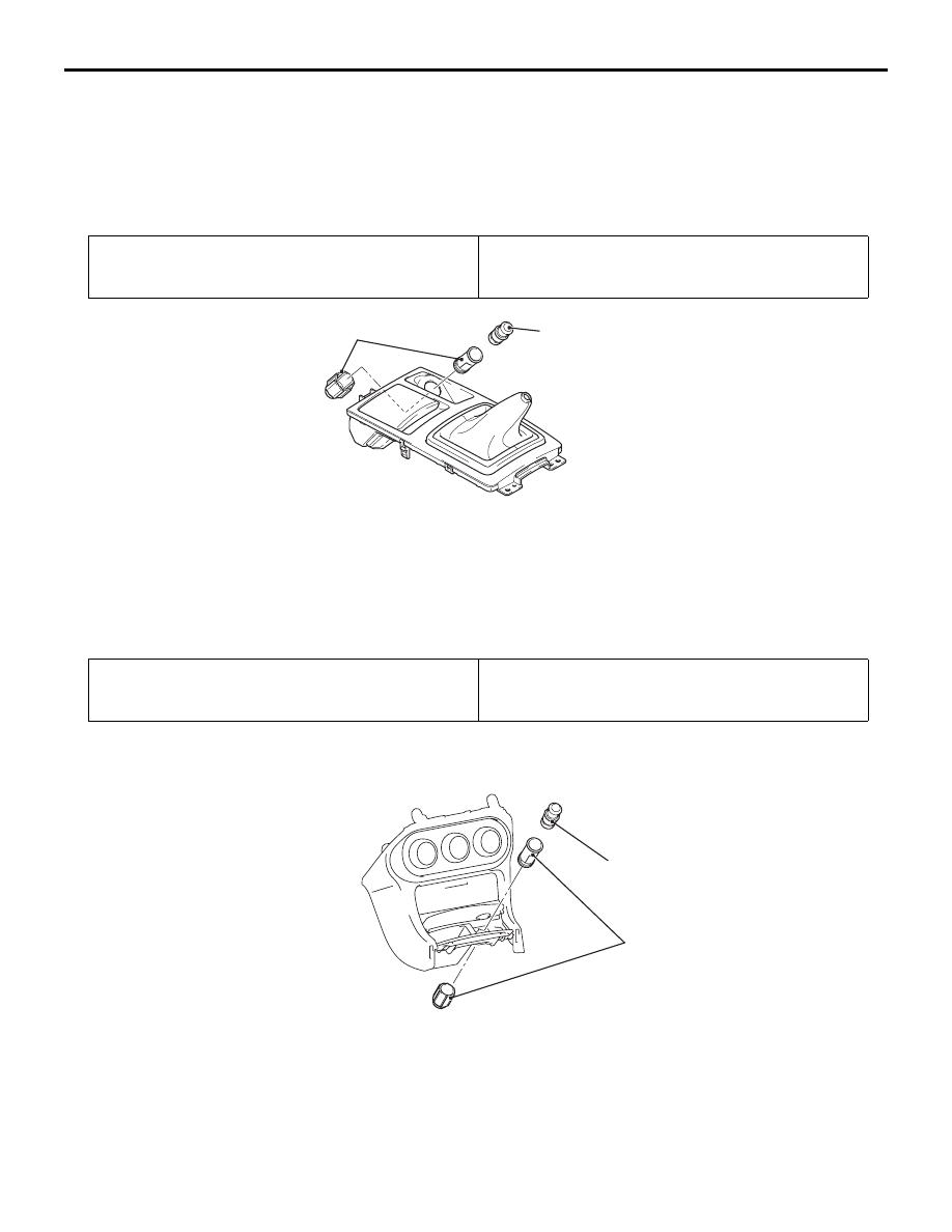
ACCESSORY SOCKET <FLOOR CONSOLE PANEL ASSEMBLY>

ACCESSORY SOCKET <INSTRUMENT PANEL CENTRE LOWER ASSEMBLY>

Removal Steps 

1.

Bulb/Harness (For illumination)

2.

Bulb

3.

Harness (For illumination)

4.

Cigar lighter

Removal Steps (Continued)

Pre-removal operation
• Removal of floor console panel assembly (Refer to 

GROUP 52A 

− Floor Console Assembly )

Post-installation operation
• Installation of floor console panel assembly (Refer to 

GROUP 52A 

− Floor Console Assembly )

AC706787

2

1

AB

Removal Steps 

1.

Accessory socket

2.

Accessory socket cap

Pre-removal operation
• Removal of Instrument panel centre lower (Refer to 

GROUP 52A 

− Instrument centre panel )

Post-installation operation
• Installation of Instrument panel centre lower (Refer to 

GROUP 52A 

− Instrument centre panel )

AC802078

1

2

AB

Removal Steps 

1.

Accessory socket

2.

Accessory socket cap

ACCESSORY SOCKET AND CIGARETTE LIGHTER

CHASSIS ELECTRICAL

54A-279

ACCESSORY SOCKET <FLOOR CONSOLE ASSEMBLY>

REMOVAL SERVICE POINT

 <<A>> REMOVAL OF ACCESSORY SOCKET 
<FLOOR CONSOLE ASSEMBLY>
Disassemble, and remove.

INSPECTION <VEHICLES WITH CIGAR 
LIGHTER>

M1542200200094

• Remove the plug and check the spot wear.

• Check if cigarette butts or foreign materials are 

deposited to the element.

Using an ohmmeter, check that the element resist-

ance value is 1.7 

Ω.

Pre-removal operation
• Removal of Floor console assembly (Refer to GROUP 

52A 

− Floor Console Assembly ).

Post-installation operation
• Installation of Floor console assembly (Refer to GROUP 

52A 

− Floor Console Assembly ).

AC801717

AC608778

AB

1

2

3

4

Removal steps 

<<

A

>>

1.

Accessory socket (positive terminal 
assembly)

2.

Accessory socket (negative 
terminal assembly)

3.

Accessory socket (socket)

4.

Accessory socket (cover)

AC102585AE

Element

Spot

Plug

COLUMN SWITCH

CHASSIS ELECTRICAL

54A-280

COLUMN SWITCH

SPECIAL TOOLS

M1543100200261

COLUMN SWITCH

CHASSIS ELECTRICAL

54A-281

Tool

Number

Name

Use

MB991955

a. MB991824
b. MB991827
c. MB991910
d. MB991911
e. MB991825
f. MB991826

M.U.T.-III sub-
assembly

a. Vehicle 

Communicati
on Interface 
(V.C.I.)

b. M.U.T.-III 

USB cable

c. M.U.T.-III 

main harness 
A (Vehicles 
with CAN 
communicatio
n system)

d. M.U.T.-III 

main harness 
B (Vehicles 
without CAN 
communicatio
n system)

e. M.U.T.-III 

measure 
adapter

f. M.U.T.-III 

trigger 
harness

CAUTION

For vehicles with CAN 
communication, use M.U.T.-III 
main harness A to send 
simulated vehicle speed. If you 
connect M.U.T.-III main harness B 
instead, the CAN communication 
does not function correctly.
Diagnosis code, service data and 
actuator test check.

MB991223

a. MB991219
b. MB991220
c. MB991221
d. MB991222

Harness set

a. Check 

harness

b. LED harness
c. LED harness 

adapter

d. Probe

Continuity check and voltage 
measurement at harness wire or 
connector

a. For checking connector pin 

contact pressure

b. For checking power supply 

circuit

c. For checking power supply 

circuit

d. For connecting a locally sourced 

tester

MB991910

MB991826

MB991955

MB991911

MB991824

MB991827

MB991825

a

b

c

d

e

f

DO NOT USE

MB991223

a

d

c

b

DO NOT USE

BA


Content   ..  152  153  154  155   ..