Mitsubishi Lancer (4A9 engine). Manual - part 144
REVERSING SENSOR SYSTEM
CHASSIS ELECTRICAL
54A-238
COMMENTS ON TROUBLE SYMPTOM
If the reversing indicator does not illuminate, the wir-
ing harness, connectors, corner sensor/back sensor-
ECU, or ETACS-ECU may be defective.
PROBABLE CAUSES
• Damaged harness wires and connectors
• Malfunction of corner sensor/back sensor-ECU
• Malfunction of the ETACS-ECU
DIAGNOSIS PROCEDURE
STEP 1. Connector check: C-43 sonar switch
connector
Q: Is the check result normal?
YES :
Go to Step 2.
NO :
Repair the defective connector.
STEP 2. Sonar switch check
Check the indicator. (Refer to )
Q: Is the check result normal?
YES :
Go to Step 3.
NO :
Replace the sonar switch.
STEP 3. M.U.T.-III other system diagnosis code
Check if the diagnosis code is set to the ETACS-
ECU.
Q: Is the check result normal?
YES :
Troubleshoot the ETACS-ECU. Refer to
ETACS-ECU
− Troubleshooting .
NO :
Go to Step 4.
STEP 4. Voltage measurement at the C-43 sonar
switch connector
(1) Disconnect the connector, and measure at the
wiring harness side.
(2) Turn the ignition switch to the "ON" position.
(3) Measure the voltage between the C-43 sonar
switch connector (terminal No. 5) and the body
earth.
OK: System voltage
Q: Is the check result normal?
YES :
Go to Step 6.
NO :
Go to Step 5.
STEP 5. Wiring harness check from C-317
ETACS-ECU connector (terminal No.5) to C-43
sonar switch connector (terminal No. 5)
• Check the communication line for open circuit or
short circuit.
NOTE: Before the wiring harness inspection, inspect
joint connector C-150, and repair if necessary.
Q: Is the check result normal?
YES :
Troubleshoot the ETACS-ECU. Refer to
Inspection Procedure 2 "The ignition switch
(IG1) signal is not received" .
NO :
Repair the wiring harness.
STEP 6. Connector check: C-40 corner sensor/
back sensor-ECU connector
Q: Is the check result normal?
YES :
Go to Step 7.
NO :
Repair the defective connector.
STEP 7. Wiring harness check from C-43 sonar
switch connector (terminal No. 6) to C-40 corner
sensor/back sensor-ECU connector (terminal No.
11).
• Check the communication line for open circuit or
short circuit.
Q: Is the check result normal?
YES :
Go to Step 8.
NO :
Repair the wiring harness.
STEP 8. Retest the system
Q: Is the check result normal?
YES :
The diagnosis is complete.
NO :
Replace the corner sensor/back sensor-
ECU.
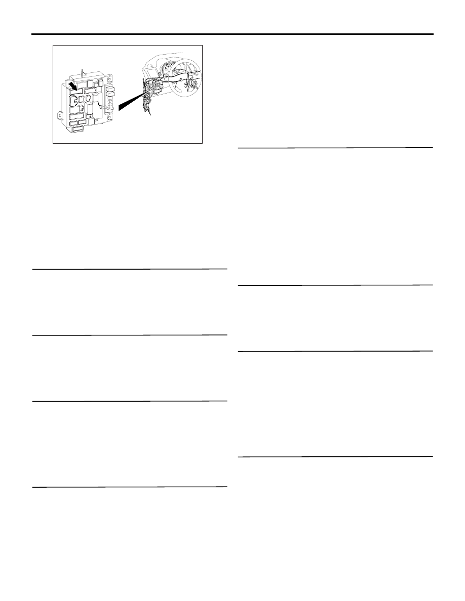
ACA00886
AL
Connector: C-317
ETACS-ECU