Mitsubishi Lancer (4A9 engine). Manual - part 141
REVERSING SENSOR SYSTEM
CHASSIS ELECTRICAL
54A-226
DIAGNOSTIC FUNCTION
• During the transmission/reception operation of
each sensor, when the corner sensor/back sen-
sor-ECU detects an open circuit abnormality
between the sensor and corner sensor/back sen-
sor-ECU, the ECU sets one of the diagnosis
codes No. B252E, No. B2530, No. B2532, and
No. 2534.
TROUBLESHOOTING HINT
• Damaged harness wires and connectors
• Sensor malfunction
• Malfunction of corner sensor/back sensor-ECU
DIAGNOSIS PROCEDURE
STEP 1. Check the following connectors.
Check the following connectors:
• F-31 Rear corner sensor (RH) connector
• F-34 Rear corner sensor (LH) connector
• F-32 Back sensor (RH) connector
• F-33 Back sensor (LH) connector
• C-40 corner sensor/back sensor-ECU connector
Q: Are all the connectors in good condition?
YES :
Go to Step 2.
NO :
Repair the defective connector.
STEP 2. Check the following wiring harness.
Check the wiring harness for open circuit between
the following connectors:
• Wiring harness from F-31 Rear corner sensor
(RH) connector terminal No. 1, 2 to C-40 corner
sensor/back sensor-ECU connector terminal No.
6, 23.
• Wiring harness from F-34 Rear corner sensor
(LH) connector terminal No. 1, 2 to C-40 corner
sensor/back sensor-ECU connector terminal No.
5, 22.
• Wiring harness from F-32 Back sensor (RH) con-
nector terminal No. 1, 2 to C-40 corner sensor/
back sensor-ECU connector terminal No. 8, 12.
• Wiring harness from F-33 Back sensor (LH) con-
nector terminal No. 1, 2 to C-40 corner sensor/
back sensor-ECU connector terminal No. 7, 21.
NOTE: Prior to the wiring harness inspection, check
intermediate connectors C-27, D-17, F-18, and repair
if necessary.
Q: Are all the wiring harness wires in good condition?
YES :
Go to Step 3.
NO :
Repair the wiring harness.
STEP 3. Confirm which reversing sensor (corner
sensor/back sensor) does not detect the
obstacle.
Q: Which reversing sensor (corner sensor/back
sensor) does not detect the obstacle?
Rear corner sensor (RH) :
Go to Step 4.
Rear corner sensor (LH) :
Go to Step 5.
Back sensor (RH) :
Go to Step 6.
Back sensor (LH) :
Go to Step 7.
STEP 4. Diagnosis code recheck
Temporarily replace the rear corner sensor (RH), and
then check if the diagnosis code No. B252E is set.
Q: Is the diagnosis code set?
ACB02645
AQ
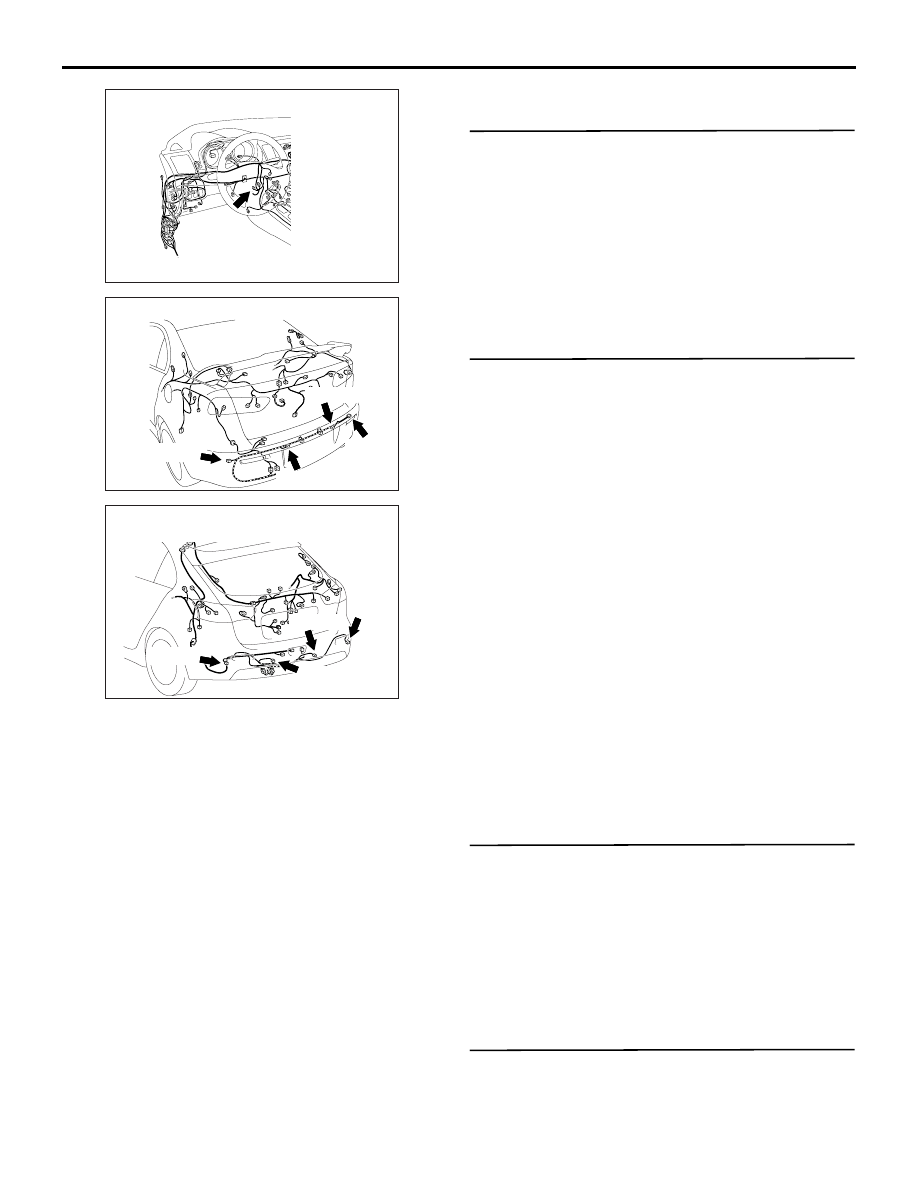
Connector: C-40
ACB02748AC
F-34 (B)
Connectors: F-31, F-32, F-33, F-34 <LANCER>
F-32 (B)
F-31 (B)
F-33 (B)
ACB02749AC
F-34 (B)
F-32 (B)
F-31 (B)
F-33 (B)
Connectors: F-31, F-32, F-33, F-34
<LANCER SPORTBACK>