Mitsubishi Lancer (4A9 engine). Manual - part 115


  Index      Mitsubishi     Mitsubishi Lancer (4A9 engine) 12GS41 & 44S - service repair manual


Search            


Content   ..  113  114  115  116   ..


Mitsubishi Lancer (4A9 engine). Manual - part 115


HEADLAMP

CHASSIS ELECTRICAL

54A-122

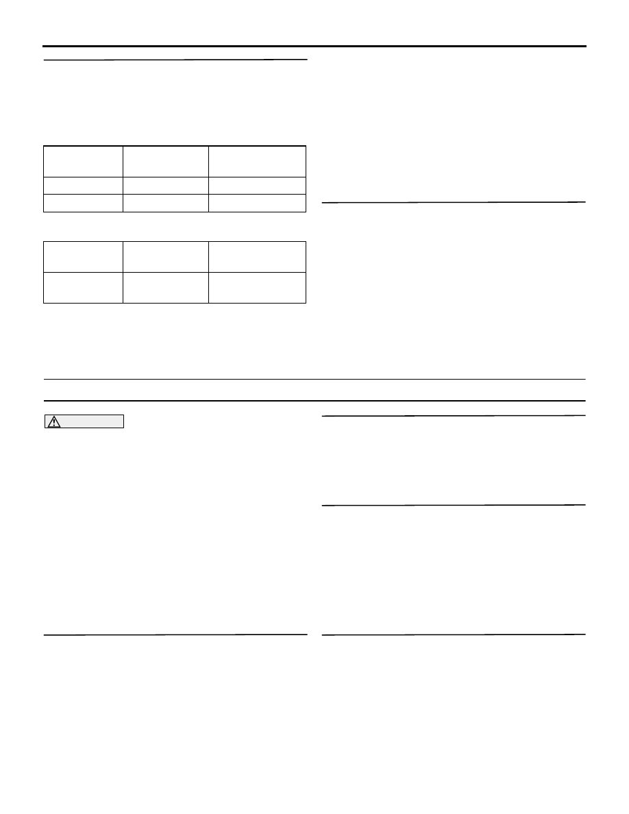
STEP 2. M.U.T.-III data list
Using the ETACS-ECU service data, check the sig-
nals related to the illumination of turn-signal lamp.

• Turn the ignition switch to the ON position.

• Turn the turn-signal lamp switch to the left posi-

tion.

• Turn the turn-signal lamp switch to the right posi-

tion.

OK: Normal conditions are displayed for all 
the items.

Q: Is the check result normal?

Normal conditions are displayed for all the items. : 

Go to Step 3.

Normal condition is not displayed for item No. 254. 

Troubleshoot the ETACS-ECU. Refer to 
Inspection Procedure 2 "The ignition switch 
(IG1) signal is not received" .

Normal condition is not displayed for item No. 343 
or 344. : 

Troubleshoot the ETACS-ECU. Refer to 

Inspection Procedure 11 "The column 
switch signal is not received" .

STEP 3. Retest the system
Check that the turn-signal lamps illuminate.

Q: Is the check result normal?

YES : 

The trouble can be an intermittent 

malfunction (Refer to GROUP 00 

− How to 

use Troubleshooting/inspection Service 
Points 

− How to Cope with Intermittent 

Malfunction ).

NO : 

Replace the ETACS-ECU.

Inspection Procedure 11: The comfort flashing function does not work normally.

CAUTION

Whenever the ECU is replaced, ensure that the 
power supply circuit, the earth circuit and the 
communication circuit are normal.
COMMENTS ON TROUBLE SYMPTOM
If the comfort flashing function does not work nor-
mally, the turn-signal lamp switch input circuit(s) and 
ETACS-ECU may have a problem.

PROBABLE CAUSES

• Malfunction of column switch

• Malfunction of the ETACS-ECU

• Damaged harness wires and connectors

DIAGNOSIS PROCEDURE

STEP 1. ETACS-ECU customise function check
Use the ETACS-ECU customise function to check 
that the "Comfort flasher" is set to "Enable."

Q: Is the check result normal?

YES : 

Go to Step 2.

NO : 

Use the ETACS-ECU customise function to 
set the "Comfort flasher" to "Enable" (Refer 
to ).

STEP 2. M.U.T.-III diagnosis code
Check if diagnosis code is set to the ETACS-ECU.

Q: Is the diagnosis code set?

YES : 

Troubleshoot the ETACS-ECU. Refer to .

NO : 

Go to Step 3.

STEP 3. Check that the turn-signal lamps 
operate.
Check that the turn-signal lamps work normally when 
the ignition switch is in the ON position.

Q: Is the check result normal?

YES : 

Go to Step 4.

NO : 

Refer to Inspection Procedure 10 "None of 
the turn-signal lamps illuminate" .

STEP 4. Retest the system
Check that the comfort flashing function works nor-
mally.

Q: Is the check result normal?

YES : 

The trouble can be an intermittent 

malfunction (Refer to GROUP 00 

− How to 

use Troubleshooting/inspection Service 
Points 

− How to Cope with Intermittent 

Malfunction ).

NO : 

Replace the ETACS-ECU.

Item No.

Item name

Normal 
condition

Item 254

IG voltage

System voltage

Item 343

Turn switch left ON

Item No.

Item name

Normal 
condition

Item 344

Turn switch 
right

ON

HEADLAMP

CHASSIS ELECTRICAL

54A-123

Inspection Procedure 12: The turn-signal indicator lamps do not illuminate.

CAUTION

Whenever the ECU is replaced, ensure that the 
power supply circuit, the earth circuit and the 
communication circuit are normal.
COMMENTS ON TROUBLE SYMPTOM
If the turn-signal lamp indicator does not illuminate 
normally, the harness in the CAN bus lines, connec-
tor(s), ETACS-ECU, or combination meter may have 
a problem.

PROBABLE CAUSES

• Malfunction of the ETACS-ECU

• Malfunction of combination meter

• Damaged harness wires and connectors

DIAGNOSIS PROCEDURE

STEP 1. Turn-signal lamp check
Check that the turn-signal lamp flashes normally 
when the turn-signal switch is operated.

Q: Is the check result normal?

YES : 

Go to Step 2.

NO : 

Refer to Inspection Procedure 10 "None of 
the turn-signal lamps illuminate" .

STEP 2. M.U.T.-III CAN bus diagnostics
Use the M.U.T.-III to diagnose the CAN bus lines.

Q: Is the check result normal?

YES : 

Go to Step 3.

NO : 

Repair the CAN bus line (Refer to GROUP 
54C 

− Troubleshooting ).

STEP 3. M.U.T.-III diagnosis code
Check if diagnosis code is set to the ETACS-ECU.

Q: Is the diagnosis code set?

YES : 

Troubleshoot the ETACS-ECU. Refer to .

NO : 

Go to Step 4.

STEP 4. M.U.T.-III actuator test
Perform the actuator test for the combination meter, 
and check that the turn-signal lamp indicator illumi-
nates (Refer to Combination meter ).

Q: Is the check result normal?

YES : 

Replace the ETACS-ECU.

NO : 

Replace the combination meter.

Inspection Procedure 13: One of the bending lamps does not illuminate.

CAUTION

Whenever the ECU is replaced, ensure that the 
power supply circuit, the earth circuit and the 
communication circuit are normal.

AC612144

AC801941

AF

Connector: A-28X

ACA00916

A-53 (B)

Connectors: A-35, A-53

AJ

A-35 (B)

ACA00892

Connector: C-14 <LHD>

AS

HEADLAMP

CHASSIS ELECTRICAL

54A-124

COMMENTS ON TROUBLE SYMPTOM
When one of the bending lamps is not turned ON, the 
harness, connector, bulb, or headlamp automatic lev-
elling-ECU may be defective.

PROBABLE CAUSES

• Malfunction of the bending lamp bulbs

• Malfunction of the headlamp automatic levelling-

ECU

• Damaged harness wires and connectors

DIAGNOSIS PROCEDURE

STEP 1. Check a trouble spot.

Q: Which bending lamp does not illuminate?

The LH-side does not illuminate. : 

Go to Step 2

The RH-side does not illuminate. : 

Go to Step 11

STEP 2. Connector check: A-35 headlamp 
assembly (LH) connector

Q: Is the check result normal?

YES : 

Go to Step 3.

NO : 

Repair the defective connector.

STEP 3. Bulb check
Check the bulb(s) of headlamp that does not illumi-
nate.

Q: Is the check result normal?

YES : 

Go to Step 4.

NO : 

Replace the bulb(s) of the lamp that does 
not illuminate.

STEP 4. Connector check: C-14 headlamp 
automatic levelling-ECU connector

Q: Is the check result normal?

YES : 

Go to Step 5.

NO : 

Repair the defective connector.

STEP 5. Voltage measurement at C-14 headlamp 
automatic levelling-ECU connector
(1) Disconnect the connector, and measure at the 

wiring harness side.

(2) Turn the ignition switch to the ON position.
(3) Turn the lighting switch to the HEAD position.
(4) Turn the steering wheel anticlockwise for 104

° or 

more.

(5) Measure the voltage between C-14 headlamp 

automatic levelling-ECU connector terminal No. 3 
and the body earth.

OK: System voltage

Q: Is the check result normal?

YES : 

Go to Step 8.

NO : 

Go to Step 6.

STEP 6. Connector check: A-28X headlamp relay 
(LO) connector

Q: Is the check result normal?

YES : 

Go to Step 7.

NO : 

Repair the defective connector.

STEP 7. Wiring harness check between C-14 
headlamp automatic levelling-ECU connector 
terminal No. 10 and A-28X headlamp relay (LO) 
connector terminal No. 3.

• Check the power supply line for open circuit and 

short circuit.

Q: Is the check result normal?

YES : 

The trouble can be an intermittent 

malfunction (Refer to GROUP 00 

− How to 

use Troubleshooting/inspection Service 
Points 

− How to Cope with Intermittent 

Malfunction ).

NO : 

Repair the wiring harness.

STEP 8. Resistance measurement at A-35 
headlamp assembly (LH) connector
(1) Disconnect the connector, and measure at the 

wiring harness side.

(2) Measure the resistance between A-35 headlamp 

assembly (LH) connector terminal No. 8 and the 
body earth.

OK: Continuity exists (2 

 or less)

Q: Is the check result normal?

YES : 

Go to Step 10.

NO : 

Go to Step 9.

ACA00895AR

Connector: C-14 <RHD>

HEADLAMP

CHASSIS ELECTRICAL

54A-125

STEP 9. Wiring harness check between A-35 
headlamp assembly (LH) connector terminal No. 
8 and body earth

• Check the earth wires for open circuit.

Q: Is the check result normal?

YES : 

The trouble can be an intermittent 

malfunction (Refer to GROUP 00 

− How to 

use Troubleshooting/inspection Service 
Points 

− How to Cope with Intermittent 

Malfunction ).

NO : 

Repair the wiring harness.

STEP 10. Wiring harness check between C-14 
headlamp automatic levelling-ECU connector 
terminal No. 3 and A-35 headlamp assembly (LH) 
connector terminal No. 7.

• Check the signal line for open circuit and short 

circuit.

Q: Is the check result normal?

YES : 

Go to Step 20.

NO : 

Repair the wiring harness.

STEP 11. Connector check: A-53 headlamp 
assembly (RH) connector

Q: Is the check result normal?

YES : 

Go to Step 12.

NO : 

Repair the defective connector.

STEP 12. Bulb check
Check the bulb(s) of headlamp that does not illumi-
nate.

Q: Is the check result normal?

YES : 

Go to Step 13.

NO : 

Replace the bulb(s) of the lamp that does 
not illuminate.

STEP 13. Connector check: C-14 headlamp 
automatic levelling-ECU connector

Q: Is the check result normal?

YES : 

Go to Step 14.

NO : 

Repair the defective connector.

STEP 14. Voltage measurement at C-14 headlamp 
automatic levelling-ECU connector
(1) Disconnect the connector, and measure at the 

wiring harness side.

(2) Turn the ignition switch to the ON position.
(3) Turn the lighting switch to the HEAD position.
(4) Turn the steering wheel clockwise for 104

° or 

more.

(5) Measure the voltage between C-14 headlamp 

automatic levelling-ECU connector terminal No. 1 
and the body earth.

OK: System voltage

Q: Is the check result normal?

YES : 

Go to Step 17.

NO : 

Go to Step 15.

STEP 15. Connector check: A-28X headlamp 
relay (LO) connector

Q: Is the check result normal?

YES : 

Go to Step 16.

NO : 

Repair the defective connector.

STEP 16. Wiring harness check between C-14 
headlamp automatic levelling-ECU connector 
terminal No. 11 and A-28X headlamp relay (LO) 
connector terminal No. 3.

• Check the power supply line for open circuit and 

short circuit.

Q: Is the check result normal?

YES : 

The trouble can be an intermittent 

malfunction (Refer to GROUP 00 

− How to 

use Troubleshooting/inspection Service 
Points 

− How to Cope with Intermittent 

Malfunction ).

NO : 

Repair the wiring harness.

STEP 17. Resistance measurement at A-53 
headlamp assembly (RH) connector
(1) Disconnect the connector, and measure at the 

wiring harness side.

(2) Measure the resistance between A-53 headlamp 

assembly (RH) connector terminal No. 8 and the 
body earth.

OK: Continuity exists (2 

 or less)

Q: Is the check result normal?

YES : 

Go to Step 19.

NO : 

Go to Step 18.

STEP 18. Wiring harness check between A-53 
headlamp assembly (RH) connector terminal No. 
8 and body earth

• Check the earth wires for open circuit.

Q: Is the check result normal?

YES : 

The trouble can be an intermittent 

malfunction (Refer to GROUP 00 

− How to 

use Troubleshooting/inspection Service 
Points 

− How to Cope with Intermittent 

Malfunction ).

NO : 

Repair the wiring harness.


Content   ..  113  114  115  116   ..