Mitsubishi Lancer (4A9 engine). Manual - part 99


  Index      Mitsubishi     Mitsubishi Lancer (4A9 engine) 12GS41 & 44S - service repair manual


Search            


Content   ..  97  98  99  100   ..


Mitsubishi Lancer (4A9 engine). Manual - part 99


COMBINATION METER

CHASSIS ELECTRICAL

54A-58

Inspection Procedure 9: The multi information display screen cannot be changed with the operation 
of the meter information switch.

CAUTION

Before replacing the combination meter, be sure 
to check that the power supply circuit, earth cir-
cuit, and communication circuit are normal.

COMMENTS ON TROUBLE SYMPTOM
When the signal from the meter information switch is 
received, the combination meter switches the multi 
information display screen. If the multi information 
display screen does not switch normally, the meter 
information switch, wiring harness, connector(s), or 
combination meter may have a problem.

PROBABLE CAUSES

• Malfunction of meter information switch

• Malfunction of combination meter

• Damaged harness wires and connectors

DIAGNOSIS PROCEDURE

STEP 1. M.U.T.-III diagnosis code
Check if diagnosis code is set to the combination 
meter.

Q: Is the diagnosis code set?

YES : 

Refer to .

NO : 

Go to Step 2.

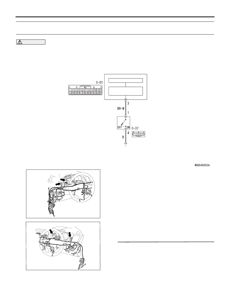
Meter Information Switch Circuit

INTERFACE
CIRCUIT

COMBINATION
METER

CPU

METER
INFORMATION
SWITCH

Wire colour code 
B : Black     LG : Light green     G : Green     L : Blue     W : White     Y : Yellow     SB : Sky blue 
BR : Brown     O : Orange     GR : Grey     R : Red     P : Pink     V : Violet     PU : Purple     SI : Silver

AC701093 BB

Connectors: C-01, C-37 <LHD>

C-01

C-37

AC701122 BQ

Connectors: C-01, C-37 <RHD>

C-01

C-37

COMBINATION METER

CHASSIS ELECTRICAL

54A-59

STEP 2. Connector check: C-37 meter 
information switch connector

Q: Is the check result normal?

YES : 

Go to Step 3.

NO : 

Repair the connector.

STEP 3. Meter information switch check
Check the meter information switch. Refer to .

Q: Is the check result normal?

YES : 

Go to Step 4.

NO : 

Replace the meter information switch.

STEP 4. Resistance measurement at the C-37 
meter information switch connector
(1) Disconnect the meter information switch 

connector, and then measure at the wiring 
harness side.

(2) Measure the resistance from C-37 meter 

information switch connector terminal No. 4 to 
body earth.

OK: Continuity exists (2 

 or less)

Q: Is the check result normal?

YES : 

Go to Step 6.

NO : 

Go to Step 5.

STEP 5. Check the wiring harness between the C-
37 meter information switch connector terminal 
No. 4 and the body earth.
Check the earth wires for open circuit.

Q: Is the check result normal?

YES : 

Go to Step 8.

NO : 

Repair the wiring harness.

STEP 6. Connector check: C-01 combination 
meter connector

Q: Is the check result normal?

YES : 

Go to Step 7.

NO : 

Repair the connector.

STEP 7. Check the wiring harness between the C-
01 combination meter connector terminal No. 3 
and the C-37 meter information switch terminal 
No. 1.
Check the output lines for open circuit and short cir-
cuit.

Q: Is the check result normal?

YES : 

Go to Step 8.

NO : 

Repair the wiring harness.

STEP 8. Retest the system
Check that the multi information display screen 
switches normally when the meter information switch 
is operated.

Q: Is the check result normal?

YES : 

The trouble can be an intermittent 

malfunction (Refer to GROUP 00 

− How to 

use Troubleshooting/Inspection Service 
Points 

− How to Cope with Intermittent 

Malfunction ).

NO : 

Replace the combination meter.

Inspection Procedure 10: Fuel Gauge does not work (other meters work).

COMMENTS ON TROUBLE SYMPTOM
If only the fuel gauge does not operate, the fuel 
pump and gauge assembly, the fuel gauge unit (sub) 
or the combination meter may be defective.

PROBABLE CAUSES

• Malfunction of fuel pump and gauge assembly

• Malfunction of the fuel gauge unit (sub)

• Malfunction of combination meter

DIAGNOSIS PROCEDURE

STEP 1. Check the diagnosis code.
Check if diagnosis code No. B1201 is set.

Q: Is the diagnosis code No. B1201 set?

YES : 

Perform the troubleshooting of when the 

diagnosis code is set (Refer to ).

NO : 

Go to Step 2.

STEP 2. fuel pump and gauge assembly and fuel 
gauge unit check
Check the fuel pump and gauge assembly and fuel 
gauge unit. Refer to .

Q: Is the check result normal?

YES : 

Go to Step 3.

NO : 

Replace the fuel pump and gauge assembly 
and fuel gauge unit.

COMBINATION METER

CHASSIS ELECTRICAL

54A-60

STEP 3. Retest the system.
 Check that the fuel gauge works normally.

Q: Is the check result normal?

YES : 

The procedure is complete.

NO : 

Replace the combination meter.

Inspection Procedure 11: Seat belt reminder function does not work normally.

CAUTION

Whenever the ECU is replaced, ensure that the 
input and output signal circuits are normal.

COMMENTS ON TROUBLE SYMPTOM
If the seat belt reminder function does not work nor-
mally, the seat belt switch input circuit, the combina-
tion meter or centre panel unit may be defective.

PROBABLE CAUSES

• Malfunction of the seat belt switch (driver’s side)

• Malfunction of the seat belt switch (passenger’s 

side)

• Malfunction of the combination meter

• Malfunction of the centre panel unit

• Damaged harness wires and connectors

ACA00891

AD

Connector: C-01 <LHD>

ACA00895AS

Connector: C-01 <RHD>

ACA00892

Connector: C-10 <LHD>

AC

C-10

ACA00895AD

Connector: C-10 <RHD>

ACB02656

Connectors: D-29, D-33 <LHD>

AB

D-29

D-33

ACB02658

Connectors: D-29, D-33 <RHD>

AB

D-33

D-29

COMBINATION METER

CHASSIS ELECTRICAL

54A-61

DIAGNOSIS PROCEDURE

STEP 1. Connector check: D-29 seat belt switch 
(driver’s side) connector, D-33 seat belt switch 
(passenger’s side) connector

Q: Is the check result normal?

YES : 

Go to Step 2.

NO : 

Repair the defective connector.

STEP 2. Check the seat belt switch.
Refer to GROUP 52A 

− Front Seat Belt .

Q: Is the check result normal?

YES : 

Go to Step 3.

NO : 

Replace the seat belt switch.

STEP 3. Resistance measurement at the D-29 
seat belt switch (driver’s side) connector, D-33 
seat belt switch (passenger’s side) connector
(1) Disconnect the connector, and measure at the 

wiring harness side.

(2) Measure the resistance between the seat belt 

switch connector terminal No. 2 and the body 
earth.

OK: Continuity exists (2 

 or less)

Q: Is the check result normal?

YES : 

Go to Step 5.

NO : 

Go to Step 4.

STEP 4. Wiring harness check from D-29 seat 
belt switch (driver’s side) connector, D-33 seat 
belt switch (passenger’s side) connector terminal 
No. 2 to body earth.
NOTE: Prior to the wiring harness inspection, check 
joint connector D-47, and repair if necessary.

• Check the earth wires for open circuit.

Q: Is the check result normal?

YES : 

The trouble can be an intermittent 

malfunction (Refer to GROUP 00 

− How to 

use Troubleshooting/inspection Service 
Points 

− How to Cope with Intermittent 

Malfunction ).

NO : 

Repair the wiring harness.

STEP 5. Connector check: C-01 combination 
meter connector

Q: Is the check result normal?

YES : 

Go to Step 6.

NO : 

Repair the defective connector.

STEP 6. Check the wiring harness from C-01 
combination meter connector terminal No.5 
<driver’s side> or 16 <passenger’s side> to D-29 
seat belt switch (driver’s side) connector, D-33 
seat belt switch (passenger’s side) connector 
terminal No. 1.
NOTE: Prior to the wiring harness inspection, check 
intermediate connector C-27, and repair if necessary.

• Check the input line for open and short circuit.

Q: Is the check result normal?

YES : 

Go to Step 7.

NO : 

Repair the wiring harness.

STEP 7. Connector check: C-10 centre panel unit 
connector

Q: Is the check result normal?

YES : 

Go to Step 8.

NO : 

Repair the defective connector.

STEP 8. Check the wiring harness from C-10 
centre panel unit connector terminal No.3 to C-01 
combination meter connector terminal No.19.

• Check the input line for open and short circuit.

Q: Is the check result normal?

YES : 

Go to Step 9.

NO : 

Repair the wiring harness.

STEP 9. Retest the system.
The seat belt reminder function should work nor-
mally.

Q: Is the check result normal?

YES <The seat belt reminder function works 
normally.> : 

The trouble can be an intermittent 

malfunction (Refer to GROUP 00 

− How to 

use Troubleshooting/inspection Service 
Points 

− How to Cope with Intermittent 

Malfunction ).

NO <Buzzers do not sound.> : 

Replace the 

combination meter.

NO <The indicator (driver’s side) does not 
illuminate.> : 

Replace the combination meter.

NO <The indicator (passenger’s side) does not 
illuminate.> : 

Replace the centre panel unit.

SERVICE DATA

M1540201000871

NOTE: Some items are not displayed on M.U.T.-III 
according to the information in the ECU.


Content   ..  97  98  99  100   ..