Mitsubishi Lancer (4A9 engine). Manual - part 88
BATTERY
CHASSIS ELECTRICAL
54A-14
REMOVAL AND INSTALLATION
M1541001301506
<1600, 1800-PETROL, 2000>
CAUTION
If the battery current sensor or engine-ECU is replaced, make the battery current sensor learn the
zero point. (Refer to GROUP 00, Precautions Before Service
− Battery Current Sensor Calibration.)
<Low CO
2
specification, FFV>
ACB01849
AB
2
5
6
7
4
9
12
11
8.5 ± 1.5 N·m
12 ± 2 N·m
4.0 ± 1.0 N·m
5.0 ± 1.0 N·m
6.0 ± 2.0 N·m
10
8
1
2
3
5.0 ± 1.0 N·m
<Low CO2 specification, FFV>
<Except Low CO2
specification, FFV>
12 ± 2 N·m
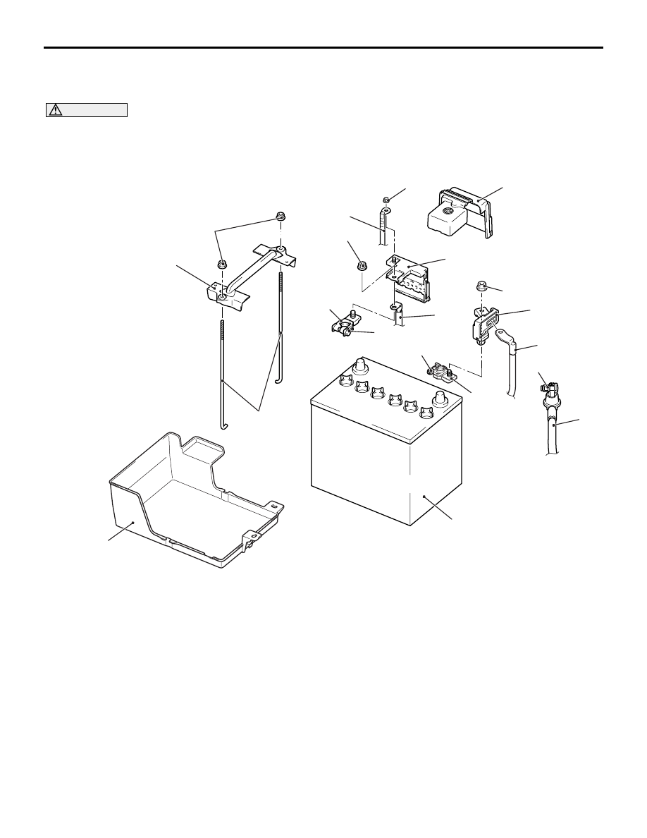
Removal steps
1.
Battery current sensor <Low CO
2
specification, FFV>
2.
Connection of the battery harness
[negative battery terminal]
3.
Battery terminal assembly [negative
battery terminal] <Low CO
2
specification, FFV>
•
Air cleaner intake duct (Refer to GROUP
15
− Air Cleaner <1800-PETROL,
2000> or <1600>).
4.
Fusible link box cover
5.
Connection of the battery harness
[positive battery terminal]
6.
Connection of the fusible link box
7.
Connection of the battery harness
[positive battery terminal]
8.
Battery terminal assembly [positive
battery terminal]
9.
Battery holder
10. Battery bolt
11. Battery
12. Battery tray
Removal steps (Continued)