Mitsubishi Lancer (4A9 engine). Manual - part 80


  Index      Mitsubishi     Mitsubishi Lancer (4A9 engine) 12GS41 & 44S - service repair manual


Search            


Content   ..  78  79  80  81   ..


Mitsubishi Lancer (4A9 engine). Manual - part 80


TROUBLESHOOTING

ACTIVE STABILITY CONTROL SYSTEM (ASC)

35C-173

The system is normal.
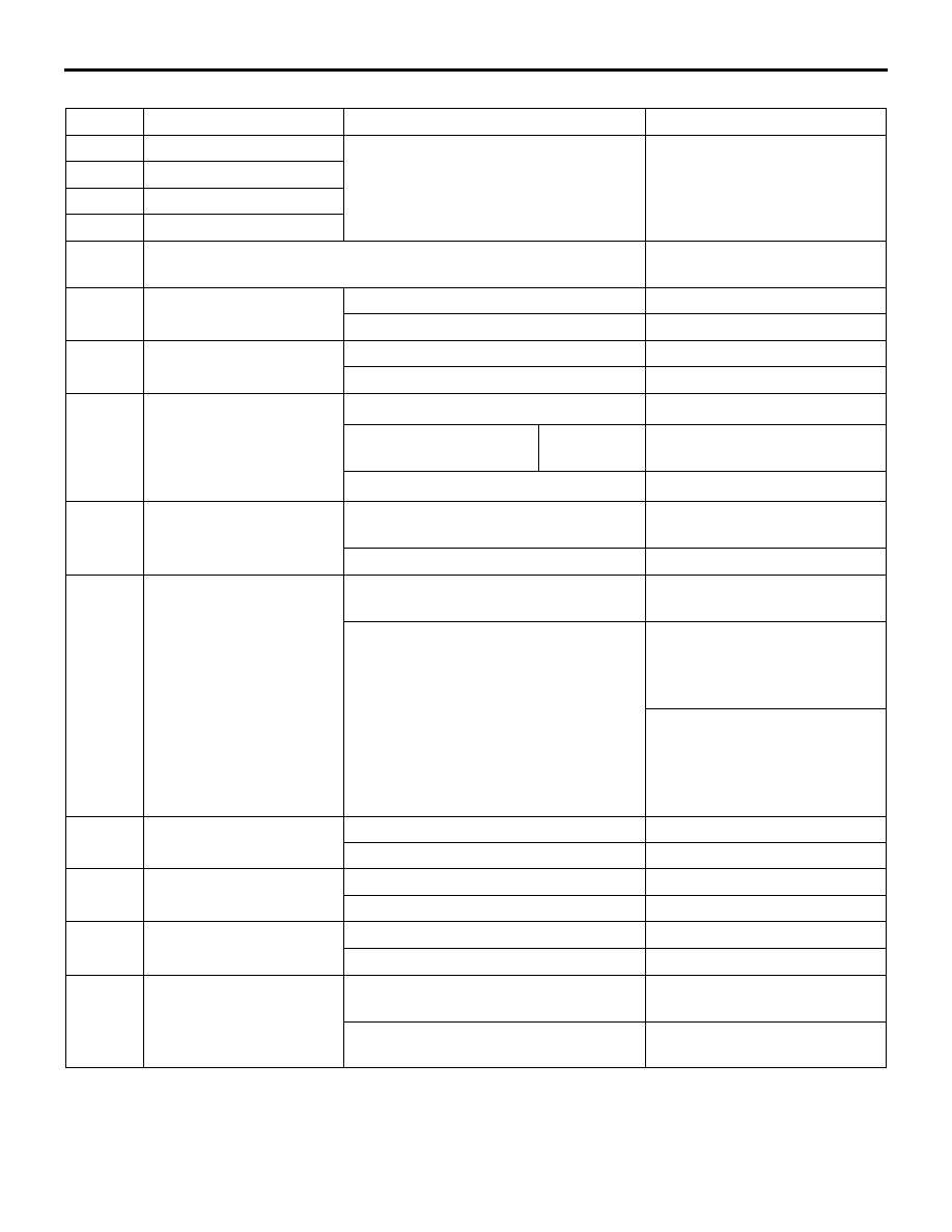
Item No. Check item

Check condition

Normal condition

01

FL wheel speed sensor

Perform a test run of the vehicle.

The speedometer display and 
the M.U.T.-III display almost 
agree with each other. (During 
stop: approximately 0.7km/h)

02

FR wheel speed sensor

03

RL wheel speed sensor

04

RR wheel speed sensor

05

Power supply voltage

System voltage (10 to 18 V 
ASC operatable range)

07

Brake switch (input)

The brake pedal is depressed.

ON

The brake pedal is released.

OFF

08

Lateral G sensor (+: left 
turn, -: right turn)

Vehicle stopped (level)

-0.11 to 0.11 G

Running

-1 to 1 G

09

G sensor (+: 
deceleration, -: 
acceleration)

Vehicle stopped (level)

0 G

*1

 (fixed value)

Vehicle stopped (level)

Idle neutral 
control 

-0.11 to 0.11 G 

Running

0 G

*1

 (fixed value)

10

Master cylinder pressure 
(+: pressure increase, -: 
pressure decrease)

The brake pedal is depressed.

Increases by the amount of 
the brake pedal depression.

The brake pedal is released.

-3 to 3 bar

11

Steering angle (+: left 
turn, -: right turn)

Vehicle stopped (the steering wheel is 
in the neutral position)

-6 to 6 deg

Running

Nearly the same as the 
steering wheel operation 
angle <-720 to 720 deg (ASC-
ECU normal detection value)>
Nearly the same as the 
steering wheel operation 
angle <-850 to 850 deg 
(Sensor normal value as a 
single unit)>

12

Yaw rate sensor (+: left 
turn, -: right turn)

Vehicle stopped (level)

-3.6 to 3.6 deg/s

Running

-100 to 100 deg/s

14

Brake switch

The brake pedal is depressed.

ON

The brake pedal is released.

OFF

15

Emission test mode

Emission test mode: ON

ON

Emission test mode: OFF

OFF

26

Brake fluid pressure 
switch

Brake fluid level is lower than the 
"LOWER" marking.

Low

Brake fluid level is higher than the 
"LOWER" marking.

Normal

TROUBLESHOOTING

ACTIVE STABILITY CONTROL SYSTEM (ASC)

35C-174

28

ASC/TCL off switch

When the ASC OFF switch is not 
operated (when the ASC control is 
available)

ON

When the ASC OFF switch is operated 
(pressed and held for 3 seconds or 
more)(when the ASC control is 
prohibited)

OFF

When the ASC OFF switch is operated 
(pressed and held for 15 seconds or 
more)(when the ASC OFF control is 
prohibited by fail-safe function)

*2

ON

45

SAS OK flag

When the steering wheel sensor 
neutral point is learned

Comp

When the steering wheel sensor 
neutral point is not learned

Not Comp

When the steering wheel sensor is 
defective

SAS fail
SAS fail&No Comp

65

Engine Speed

When the accelerator pedal is 
depressed (engine started)

The tachometer display and 
the M.U.T.-III display almost 
agree with each other.

66

Engine torque

Displays the engine torque.

67

APS

Displays the accelerator pedal 
opening angle.

68

Allow ESP torque request

Permitted

70

Target gear

When the selector lever is operated

Displays the selector lever 
position.

71

Actual gear

72

Master cylinder pressure 
Offset

The difference between the neutral 
position that was input to the ASC-
ECU before the master cylinder 
pressure sensor calibration and the 
neutral position after the calibration.

-8 to 8 bar

73

Lateral G sensor offset

The difference between the neutral 
position that was input to the ASC-
ECU before the G and yaw rate sensor 
calibration and the neutral position 
after the calibration.

-0.15 to 0.15 G

86

Ignition switch

Ignition switch: ON

ON

87

Ignition switch (input)

Ignition switch: ON

ON

88

Vehicle speed

Perform a test run of the vehicle.

The speedometer display and 
the M.U.T.-III display almost 
agree with each other.

91

Brake pressure sensor

The brake pedal is depressed.

ON

The brake pedal is released.

OFF

Item No. Check item

Check condition

Normal condition

TROUBLESHOOTING

ACTIVE STABILITY CONTROL SYSTEM (ASC)

35C-175

NOTE: 

.

*1

: The G and yaw rate sensor does not detect longitudinal acceleration of a vehicle, thus "0 G" is always 

set.

*2

: When the ASC OFF switch is pressed and held for 15 seconds, the ASC system returns to the ON sta-

tus.

System shutdown by ECU
While ASC-ECU is disabled by the diagnostic func-
tion, the M.U.T.-III displayed data is different from the 
actual measurement.

ACTUATOR TEST TABLE

M1355001600343

Using M.U.T.-III, the following actuators can be forci-
bly operated:

96

G sensor offset

The difference between the neutral 
position that was input to ASC-ECU 
before the G and yaw rate sensor 
calibration and the neutral position 
after the calibration.

0 G

*1

 (fixed value)

The difference between 
the neutral position that 
was input to ASC-ECU 
before the G and yaw 
rate sensor calibration 
and the neutral position 
after the calibration.

Idle neutral 
control 

-0.15 to 0.15 G 

97

Yaw rate sensor offset

The difference between the neutral 
position that was input to the ASC-
ECU before the G and yaw rate sensor 
calibration and the neutral position 
after the calibration.

-6.0 to 6.0 deg/s

105

Power supply voltage (input)

System voltage (10 to 18 V 
ASC operatable range)

120

Parking brake switch 
(Input)

When the parking brake lever is pulled 
up:

ON

When the parking brake lever is 
released:

OFF

128

A.S.C./TCL off switch 
(input)

The ASC OFF switch is pressed.

ON

The ASC OFF switch is not operated.

OFF

138

ESS request

ASC-ECU is demanding the ESS 
operation of ETACS-ECU.

ON

ASC-ECU is not demanding the ESS 
operation of ETACS-ECU.

OFF

Item No. Check item

Check condition

Normal condition

TROUBLESHOOTING

ACTIVE STABILITY CONTROL SYSTEM (ASC)

35C-176

NOTE: 

.

ABS and ASC are operated by ASC-ECU.

When ASC-ECU is disabled due to the fail-safe 
function, the actuator test cannot be performed.

The actuator test can be performed only when 
the vehicle is stationary.

While the actuator test is performed, the ABS 
warning lamp flashes at a rate of 2 Hz.

While the actuator test is performed, the ASC 
warning display and ASC OFF display illuminate.

After the actuator test has been performed, the 
brake warning lamp, ABS warning lamp, ASC 
operation display, and ASC OFF display illumi-
nate until the ignition switch is turned to ON again 
or the communication between M.U.T.-III and 
ASC-ECU is terminated.

Actuator test specifications

Item No.

Check item

Driven component

01

FL wheel ABS drive

Solenoid valve for the corresponding 
channel of the hydraulic unit and pump 
motor (simplified inspection mode)

02

FR wheel ABS drive

03

RL wheel ABS drive

04

RR wheel ABS drive

05

FL wheel TCL drive

06

FR wheel TCL drive

07

RL wheel TCL drive

08

RR wheel TCL drive

09

Engine TCL drive

Outputs the engine torque control signal 
(engine torque = 0 N

⋅m) to the engine 

ECU for three seconds.

10

ESS test mode

ASC-ECU requires an ESS operation of 
ETACS-ECU.


Content   ..  78  79  80  81   ..