Mitsubishi Lancer (4A9 engine). Manual - part 60


  Index      Mitsubishi     Mitsubishi Lancer (4A9 engine) 12GS41 & 44S - service repair manual


Search            


Content   ..  58  59  60  61   ..


Mitsubishi Lancer (4A9 engine). Manual - part 60


TROUBLESHOOTING

ACTIVE STABILITY CONTROL SYSTEM (ASC)

35C-93

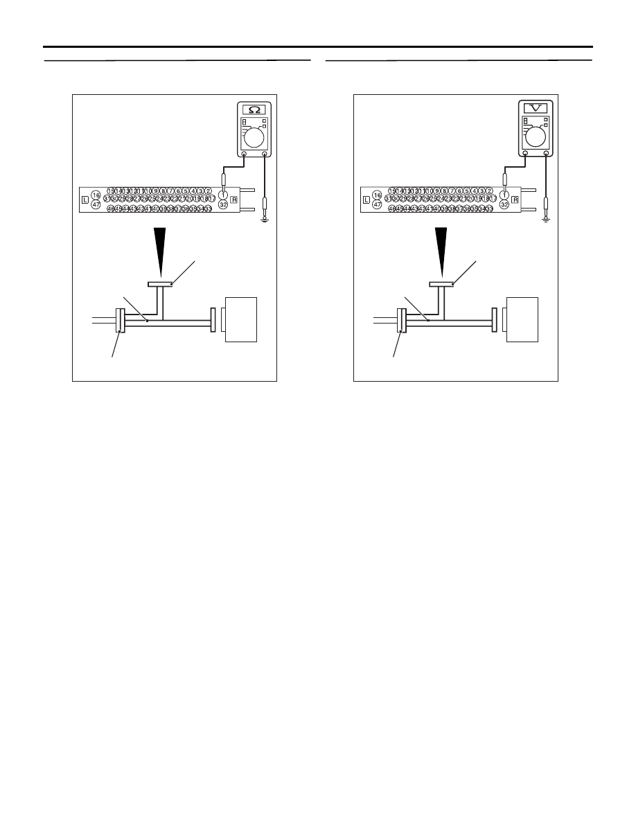
STEP 7. Resistance measurement at A-58 ASC-
ECU connector

AC606869FS

ASC-ECU

MB991997

Check harness

A-58 ASC-ECU
harness connector

(1) Disconnect the ASC-ECU connector, connect 

special tool ASC check harness (MB991997) to 
the harness-side connector, and then measure 
the resistance at the special tool connector side.
NOTE: Do not connect the special tool ASC 
check harness (MB991997) to ASC-ECU.

(2) Disconnect the fusible link No.26.
(3) Measure the resistance between the terminal 

No.1 and the body earth.

OK: No continuity

Q: Is the check result normal?

YES : 

Replace the fusible link No.26. Then go to 

Step 11.

NO : 

The short circuit may be present in the 
power supply circuit. Repair the wiring 
harness between the A-58 ASC-ECU 
connector terminal No.1 and the fusible link 
No.26, and then replace the fusible link 
No.26. Then go to Step 11.

STEP 8. Voltage measurement at the A-58 ASC-
ECU connector

AC606869DI

ASC-ECU

MB991997

Check harness

A-58 ASC-ECU
harness connector

(1) Disconnect the ASC-ECU connector, connect 

special tool ASC check harness (MB991997) to 
the harness-side connector, and then measure 
the voltage at the special tool connector side.
NOTE: Do not connect the special tool ASC 
check harness (MB991997) to ASC-ECU.

(2) Measure the voltage between the terminal No.1 

and the body earth.

OK: Approximately system voltage

Q: Is the check result normal?

YES : 

Go to Step 9.

NO : 

The open circuit may be present in the 
power supply circuit. Repair the wiring 
harness between the A-58 ASC-ECU 
connector terminal No.1 and the fusible link 
No.26. Then go to Step 11.

TROUBLESHOOTING

ACTIVE STABILITY CONTROL SYSTEM (ASC)

35C-94

STEP 9. Resistance measurement at A-58 ASC-
ECU connector

AC606869DJ

ASC-ECU

MB991997

Check harness

A-58 ASC-ECU
harness connector

(1) Disconnect the ASC-ECU connector, connect 

special tool ASC check harness (MB991997) to 
the harness-side connector, and then measure 
the resistance at the special tool connector side.
NOTE: Do not connect the special tool ASC 
check harness (MB991997) to ASC-ECU.

(2) Measure the resistance between the terminal 

No.16 and the body earth, and between the 
terminal No.47 and the body earth.

OK: Continuity exists (2 

 or less)

Q: Is the check result normal?

YES : 

Go to Step 10.

NO : 

An open circuit may be present in the earth 
circuit. Repair the wiring harness between 
the A-58 ASC-ECU connector terminal 
No.16 and the body earth, and between the 
A-58 ASC-ECU connector terminal No.47 
and the body earth. Then go to Step 11.

STEP 10. Check whether the diagnosis code is 
reset.
(1) Erase the diagnosis code.
(2) Drive the vehicle at 20 km/h or higher.

NOTE: The ABS warning lamp does not turn OFF 
in some cases unless the vehicle runs at 20 km/h 
or higher.

Q: Is the diagnosis code No. C2116 set?

YES : 

Replace the hydraulic unit (integrated with 

ASC-ECU) (Refer to 

P.35C-185

). Then go 

to Step 11.

NO : 

Intermittent malfunction (Refer to GROUP 
00 

− How to Use Troubleshooting/How to 

Cope with Intermittent Malfunctions ).

STEP 11. Check whether the diagnosis code is 
reset.
(1) Erase the diagnosis code.
(2) Drive the vehicle at 20 km/h or higher.

NOTE: The ABS warning lamp does not turn OFF 
in some cases unless the vehicle runs at 20 km/h 
or higher.

Q: Is the diagnosis code No. C2116 set?

YES : 

Return to Step 1.

NO : 

This diagnosis is complete.

Code No. C121D Abnormality in brake fluid pressure sensor circuit

CAUTION

• If there is any problem in the CAN bus lines, 

an incorrect diagnosis code may be set. Prior 
to this diagnosis, diagnose the CAN bus lines 
(Refer to GROUP 54C 

 CAN Bus Diagnostics 

Table ).

• When the hydraulic unit (integrated with ASC-

ECU) is replaced, always carry out the calibra-
tion of the steering wheel sensor, the G and 
yaw rate sensor and brake fluid pressure sen-
sor (Refer to 

P.35C-182

P.35C-183

 an

P.35C-

184

).

• Whenever ECU is replaced, ensure that the 

CAN bus lines are normal.

OPERATION
The hydraulic sensor is incorporated in the hydraulic 
unit. When the brake pedal is depressed, the pres-
sure sensor detects the brake pressure applied from 
the master cylinder, converts this pressure into the 
voltage signal, and outputs it.

DIAGNOSIS CODE SET CONDITIONS
When the pressure sensor output signal is not within 
the standard value range, ASC-ECU sets this diag-
nosis code.

TROUBLESHOOTING

ACTIVE STABILITY CONTROL SYSTEM (ASC)

35C-95

PROBABLE CAUSES

• Incorrect brake pedal height

• Incorrect adjustment of the stop lamp switch

• Master cylinder malfunction

• Brake booster malfunction

• ASC-ECU malfunction

DIAGNOSIS PROCEDURE

STEP 1. M.U.T.-III CAN bus diagnostics
Use M.U.T.-III to diagnose the CAN bus lines.

Q: Is the check result normal?

YES : 

Go to Step 3.

NO : 

Repair the CAN bus lines (Refer to GROUP 
54C 

− CAN Bus Diagnostics Table ). On 

completion, go to Step 2.

STEP 2. Diagnosis code recheck after resetting 
CAN bus lines

Q: Is diagnosis code No. C121D set?

YES : 

Go to Step 3.

NO : 

This diagnosis is complete.

STEP 3. Brake pedal check
Refer to GROUP 35A 

− On-vehicle Service/Brake 

Pedal Check and Adjustment .

Q: Is the check result normal?

YES : 

Go to Step 4.

NO : 

Go to GROUP 35A 

− On-vehicle Service/

Brake Pedal Check and Adjustment . Then 
go to Step 7.

STEP 4. Check the installation condition of the 
stop lamp switch.
Refer to GROUP 35A 

− On-vehicle Service/Brake 

Pedal Check and Adjustment .

Q: Is the check result normal?

YES : 

Go to Step 5.

NO : 

Install the stop lamp switch correctly (Refer 
to GROUP 35A 

− On-vehicle Service/Brake 

Pedal Check and Adjustment .), and then go 
to Step 7.

STEP 5. Brake booster check
Refer to GROUP 35A 

− On-vehicle Service/Brake 

Booster Operating Check .

Q: Is the check result normal?

YES : 

Go to Step 6.

NO : 

After replacing the brake booster, go to Step 
7.

STEP 6. Check whether the diagnosis code is 
reset.
Erase the diagnosis code.

Q: Is diagnosis code No.C121D set?

YES : 

Replace the hydraulic unit (integrated with 

ASC-ECU) (Refer to 

P.35C-185

). Then go 

to Step 7.

NO : 

The trouble can be an intermittent 
malfunction (Refer to GROUP 00 

− How to 

Use Troubleshooting/How to Cope with 
Intermittent Malfunctions ).

STEP 7. Check whether the diagnosis code is 
reset.
Erase the diagnosis code.

Q: Is diagnosis code No.C121D set?

YES : 

Return to Step 1.

NO : 

This diagnosis is complete.

TROUBLESHOOTING

ACTIVE STABILITY CONTROL SYSTEM (ASC)

35C-96

Code No. C121E Abnormality in brake fluid pressure sensor output signal

CAUTION

• If there is any problem in the CAN bus lines, 

an incorrect diagnosis code may be set. Prior 
to this diagnosis, diagnose the CAN bus lines 
(Refer to GROUP 54C 

 CAN Bus Diagnostics 

Table ).

• Whenever ECU is replaced, ensure that the 

CAN bus lines are normal.

• When the hydraulic unit (integrated with ASC-

ECU) is replaced, always carry out the calibra-
tion of the steering wheel sensor, the G and 
yaw rate sensor and brake fluid pressure sen-
sor (Refer to 

P.35C-182

P.35C-183

 an

P.35C-

184

).

OPERATION
The hydraulic sensor is incorporated in the hydraulic 
unit. When the brake pedal is depressed, the pres-
sure sensor detects the brake pressure applied from 
the master cylinder, converts this pressure into the 
voltage signal, and outputs it.

DIAGNOSIS CODE SET CONDITIONS
This diagnosis codes will be set under the cases 
below:

• When the pressure sensor offset is not within the 

standard value range

• When the estimated pressure sensor tempera-

ture is not normal

PROBABLE CAUSES

• Incorrect adjustment of brake pedal height

• Master cylinder malfunction

• Brake booster malfunction

• Incorrect installation position of stop lamp switch

• Malfunction of the stop lamp switch

• Brake drag

• ASC-ECU malfunction

DIAGNOSIS PROCEDURE

STEP 1. M.U.T.-III CAN bus diagnosis
Use M.U.T.-III to diagnose the CAN bus lines.

Q: Is the check result normal?

YES : 

Go to Step 3.

NO : 

Repair the CAN bus lines (Refer to GROUP 
54C 

− CAN Bus Diagnostics Table ). On 

completion, go to Step 2.

STEP 2. Diagnosis code recheck after resetting 
CAN bus lines

Q: Is the diagnosis code No. C121E set?

YES : 

Go to Step 3.

NO : 

This diagnosis is complete.

STEP 3. Brake pedal check
Refer to GROUP 35A 

− On-vehicle Service/Brake 

Pedal Check and Adjustment .

Q: Is the check result normal?

YES : 

Go to Step 4.

NO : 

Go to GROUP 35A 

− On-vehicle Service/

Brake Pedal Check and Adjustment . Then 
go to Step 9.

STEP 4. Check for stop lamp switch installation
Refer to GROUP 35A 

− On-vehicle Service/Brake 

Pedal Check and Adjustment .

Q: Is the check result normal?

YES : 

Go to Step 5.

NO : 

Install the stop lamp switch correctly (Refer 
to GROUP 35A 

− On-vehicle Service/Brake 

Pedal Check and Adjustment .), and then go 
to Step 9.

STEP 5. Stop lamp switch continuity check
(1) Remove the stop lamp switch (Refer to GROUP 


Content   ..  58  59  60  61   ..