Mitsubishi Lancer (4A9 engine). Manual - part 54
TROUBLESHOOTING
ACTIVE STABILITY CONTROL SYSTEM (ASC)
35C-69
STEP 5. Connector check: A-58 ASC-ECU
connector, A-08 front wheel speed sensor <LH>
connector
Q: Is the check result normal?
YES :
Go to Step 6.
NO :
Repair the defective connector. Then go to
Step 13.
STEP 6. Wiring harness check between A-58
ASC-ECU connector terminal No.45 and A-08
front wheel speed sensor <LH> connector
terminal No.1 and between A-58 ASC-ECU
connector terminal No.46 and A-08 front wheel
speed sensor <LH> connector terminal No.2.
Q: Is the check result normal?
YES :
Go to Step 7.
NO :
Repair the wiring harness. Then go to Step
13.
STEP 7. Check for wheel speed sensor <FL>
installation
Check how the wheel speed sensor <FL> is installed
(Disconnection of wheel speed sensor <FL>, loose
mounting bolt, etc.).
Q: Is the check result normal?
YES :
Go to Step 8.
NO :
Reinstall the wheel speed sensor <FL>
correctly (Refer to
). Then go to
Step 8.
STEP 8. Check for wheel speed sensor <FL>
output current
Refer to
Q: Is the check result normal?
YES :
Go to Step 9.
NO :
Replace the wheel speed sensor <FL>
(Refer to
). Then go to Step 12.
STEP 9. Check for wheel bearing looseness
NOTE: Loose wheel bearing may increase the gap
between the wheel speed sensor <FL> and the
wheel speed detection magnet encoder. Check the
wheel bearing <FL> for looseness. (Refer to GROUP
26
−
Wheel Bearing Axial Play Check .)
Q: Is the check result normal?
YES :
Go to Step 10.
NO :
Replace the wheel bearing <FL> (Refer to
GROUP 26
− Front Axle Hub Assembly ).
Then go to Step 13.
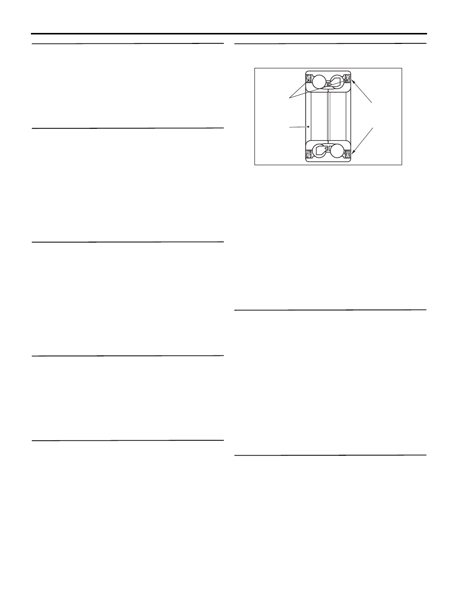
STEP 10. Check of wheel speed detection
encoder
AC504925
Oil seal
Magnetic
encoder
AC
Wheel
bearing
Check the encoder for adhesion of foreign materials
or deformation.
Q: Is the check result normal?
YES :
Go to Step 11.
NO (Adhesion of foreign materials) :
Remove the
foreign materials and clean the encoder so
as not to disturb the magnetization pattern
on it while taking care of the magnet,
magnetic substance, and magnetic
attraction. Then go to Step 13.
NO (Deformation) :
Replace the wheel bearing
<FL> (Refer to GROUP 26
− Front Axle Hub
Assembly ). Then go to Step 13.
STEP 11. Check whether the diagnosis code is
reset.
(1) Erase the diagnosis code.
(2) Drive the vehicle at 20 km/h or higher.
NOTE: The ABS warning lamp does not turn OFF
in some cases unless the vehicle runs at 20 km/h
or higher.
Q: Is the diagnosis code No.C1046 set?
YES :
Replace the wheel speed sensor <FL>
). Then go to Step 12.
NO :
Intermittent malfunction (Refer to GROUP
00
− How to Use Troubleshooting/How to
Cope with Intermittent Malfunctions).
STEP 12. Check whether the diagnosis code is
reset.
(1) Erase the diagnosis code.
(2) Drive the vehicle at 20 km/h or higher.
NOTE: The ABS warning lamp does not turn OFF
in some cases unless the vehicle runs at 20 km/h
or higher.
Q: Is the diagnosis code No.C1046 set?