Mitsubishi Lancer (4A9 engine). Manual - part 41


  Index      Mitsubishi     Mitsubishi Lancer (4A9 engine) 12GS41 & 44S - service repair manual


Search            


Content   ..  39  40  41  42   ..


Mitsubishi Lancer (4A9 engine). Manual - part 41


TROUBLESHOOTING

ACTIVE STABILITY CONTROL SYSTEM (ASC)

35C-17

C102B

Abnormality in RR wheel speed sensor circuit

P.35C-31

C1011

Abnormality in FL wheel speed sensor signal

P.35C-36

C101C

Abnormality in FR wheel speed sensor signal

P.35C-39

C1027

Abnormality in RL wheel speed sensor signal

P.35C-43

C1032

Abnormality in RR wheel speed sensor signal

P.35C-47

C1014

Mutual monitoring of FL wheel speed sensor

P.35C-50

C101F

Mutual monitoring of FR wheel speed sensor

P.35C-52

C102A

Mutual monitoring of RL wheel speed sensor

P.35C-54

C1035

Mutual monitoring of RR wheel speed sensor

P.35C-56

C1041

Abnormality in periodical signal for FL wheel speed sensor

P.35C-58

C1042

Abnormality in periodical signal for FR wheel speed sensor

P.35C-60

C1043

Abnormality in periodical signal for RL wheel speed sensor

P.35C-62

C1044

Abnormality in periodical signal for RR wheel speed sensor

P.35C-64

C1046

FL wheel speed sensor control phase time exceeded

P.35C-67

C1047

FR wheel speed sensor control phase time exceeded

P.35C-70

C1048

RL wheel speed sensor control phase time exceeded

P.35C-74

C1049

RR wheel speed sensor control phase time exceeded

P.35C-78

C104B

Abnormality in FL wheel inlet valve system

P.35C-82

C104F

Abnormality in FR wheel inlet valve system

C1053

Abnormality in RL wheel inlet valve system

C1057

Abnormality in RR wheel inlet valve system

C105F

Abnormality in FL wheel outlet valve system

C1063

Abnormality in FR wheel outlet valve system

C1067

Abnormality in RL wheel outlet valve system

C105B

Abnormality in RR wheel outlet valve system

C1200

Abnormality in FL/RR wheel cut valve system

C1204

Abnormality in FR/RL wheel cut valve system

C1208

Abnormality in FL/RR wheel suction valve system

C120C

Abnormality in FR/RL wheel suction valve system

C2104

Faulty valve power supply circuit

P.35C-83

C1073

Faulty motor drive circuit

P.35C-87

C2116

Low or high power supply voltage in pump motor

P.35C-91

C121D

Abnormality in brake fluid pressure sensor circuit

P.35C-94

C121E

Abnormality in brake fluid pressure sensor output signal

P.35C-96

C1000

Abnormality in stop lamp switch circuit

P.35C-98

C123B

Prolonged operation of ASC

P.35C-102

C2200

Abnormality in ASC-ECU
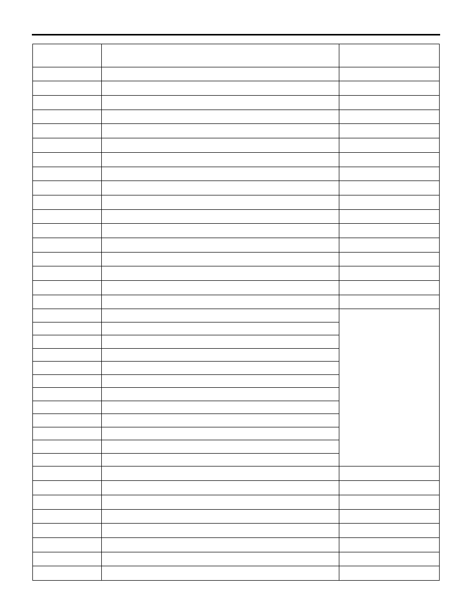
P.35C-104

Diagnosis code 
No.

Item

Reference page

TROUBLESHOOTING

ACTIVE STABILITY CONTROL SYSTEM (ASC)

35C-18

C2101

Abnormality in battery 
voltage (high voltage)

18.0 

± 1.0 V or more

P.35C-104

C1395

Brake fluid filling not completed

P.35C-105

C121C

Torque request signal rejection

P.35C-106

C1290

CAN time-out error

P.35C-107

C2203

Chassis No. not programmed

P.35C-108

C2206

Re-execution of variant coding

P.35C-109

C123C

Abnormality in G and yaw 
rate sensor output value

Abnormality in lateral G and 
yaw rate output value

P.35C-110

C2204

Internal abnormality in G and yaw rate sensor

P.35C-113

C2111

Brake fluid pressure sensor 
power supply circuit

Low input

P.35C-115

C2112

Brake fluid pressure sensor 
power supply circuit

High input

C2114

Abnormality in G and yaw 
rate sensor operation voltage

Low voltage (below 6.5 

± 0.5 V)

P.35C-116

C2115

Abnormality in G and yaw 
rate sensor operation voltage

High voltage (18.0 

± 1.0 V or 

more)

C123A

Abnormality in sensor calibration

P.35C-119

C1219

Abnormality in steering wheel sensor signal

P.35C-120

C121A

Abnormality in steering wheel 
sensor calibration

Steering wheel sensor neutral 
point not learned

P.35C-122

C2205

Internal abnormality in steering wheel sensor

P.35C-123

C2002

Valve calibration not completed

P.35C-123

C2003

Control parameter not implement

P.35C-124

C1608

Implausible diagnosis data

P.35C-126

U0001

Bus-off

P.35C-129

U0100

Engine time-out error

P.35C-131

U0101

A/T or CVT time-out error

U0126

Steering wheel sensor time-out error

U0141

ETACS time-out error

U0125

G and yaw rate sensor message time-out error/message error

P.35C-133

U0401

Engine signal malfunction detected

P.35C-135

U0404

Abnormality in AS&G signal

P.35C-130

U0428

Communication error in steering wheel sensor

P.35C-136

U1003

G and yaw rate sensor bus-off

P.35C-137

U1004

AS&G CAN time-out

P.35C-132

U1415

Variant coding not implemented

P.35C-139

U1417

Variant coding value invalid (includes faulty installation)

P.35C-140

Diagnosis code 
No.

Item

Reference page

TROUBLESHOOTING

ACTIVE STABILITY CONTROL SYSTEM (ASC)

35C-19

DIAGNOSIS CODE PROCEDURES

Code No. C100A Abnormality in FL wheel speed sensor circuit

Wheel Speed Sensor Circuit

ASC-ECU

(LH)

(LH)

(RH)

(RH)

FRONT WHEEL SPEED SENSOR

REAR WHEEL SPEED SENSOR

Wire colour code 
B : Black     LG : Light green     G : Green     L : Blue     W : White     Y : Yellow     SB : Sky blue 
BR : Brown     O : Orange     GR : Grey     R : Red     P : Pink     V : Violet     PU : Purple     SI : Silver

ACB02565

AC612690

AP

Connector: A-08 <LHD>

A-08 (B)

AC701238 AE

Connectors: A-08, A-58 <RHD>

A-58 (B)

A-08 (B)

AC701229AH

Connector: A-58 <LHD>

A-58 (B)

TROUBLESHOOTING

ACTIVE STABILITY CONTROL SYSTEM (ASC)

35C-20

CAUTION

• If there is any problem in the CAN bus lines, 

an incorrect diagnosis code may be set. Prior 
to this diagnosis, diagnose the CAN bus lines 
(Refer to GROUP 54C 

 CAN Bus Diagnostics 

Table ).

• Whenever ECU is replaced, ensure that the 

CAN bus lines are normal.

• When the hydraulic unit (integrated with ASC-

ECU) is replaced, always carry out the calibra-
tion of the steering wheel sensor, the G and 
yaw rate sensor and brake fluid pressure sen-
sor (Refer to 

P.35C-182

P.35C-183

 an

P.35C-

184

).

OPERATION

• The wheel speed sensor is a kind of a pulse gen-

erator. It consists of encoders (a plate on which 
north and south pole sides of the magnets are 
arranged alternately) for detecting the wheel 
speed which rotates at the same speed of the 
wheels and wheel speed sensors. This sensor 
outputs frequency pulse signals in proportion to 
the wheel speed.

• The pulse signals, which the wheel speed sensor 

creates, are sent to ASC-ECU. ASC-ECU uses 
the frequency of the pulse signals to determine 
the wheel speed.

DIAGNOSIS CODE SET CONDITIONS
ASC-ECU monitors the voltage fluctuation in each 
wheel speed sensor circuit. If ASC-ECU detects the 
open or short circuit in the circuit, it will set a diagno-
sis code.

PROBABLE CAUSES

Current trouble

• Damaged wiring harness and connectors

• Noise interference

• Malfunction of wheel speed sensor

• Malfunction of ASC-ECU

Past trouble

• Carry out diagnosis with particular emphasis on 

wiring harness and connector failures between 
ASC-ECU and the wheel speed sensor. For diag-
nosis procedures, refer to How to treat past trou-
ble (GROUP 00 

− How to Use Troubleshooting/

How to Treat Past Trouble ).

DIAGNOSTIC PROCEDURE

STEP 1. M.U.T.-III CAN bus diagnostics
Use M.U.T.-III to diagnose the CAN bus lines.

Q: Is the check result normal?

YES : 

Go to Step 3.

NO : 

Repair the CAN bus lines (Refer to GROUP 
54C 

− CAN Bus Diagnostics Table ). On 

completion, go to Step 2.

STEP 2. Diagnosis code recheck after resetting 
CAN bus lines

Q: Is diagnosis code No. C100A set?

YES : 

Go to Step 3.

NO : 

This diagnosis is complete.

STEP 3. M.U.T.-III data list
Check the following data list (Refer to 

P.35C-172

).

• Item No.01: FL wheel speed sensor

Q: Is the check result normal?

YES : 

Go to Step 12.

NO : 

Go to Step 4.


Content   ..  39  40  41  42   ..