Mitsubishi Evolution X. Manual - part 995
RADIO AND CD PLAYER
TSB Revision
CHASSIS ELECTRICAL
54A-341
.
COMMENTS ON TROUBLE SYMPTOM
When the audio does not operate normally by operating the
audio control unit of the center panel unit, the radio and CD
player, center panel unit, or the power supply circuit system of
center panel unit may be faulty.
.
PROBABLE CAUSES
• The radio and CD player may be defective.
• The center panel unit may be defective.
• Damaged harness wires and connectors
DIAGNOSIS
Required Special Tools:
• MB991223: Harness Set
• MB992006: Extra Fine Probe
STEP 1. Check center panel unit connector C-124 and
radio and CD player connector C-109 for loose, corroded
or damaged terminals, or terminals pushed back in the
connector.
Q: Are center panel unit connector C-124 and radio and CD
player connector C-109 in good condition?
YES : Go to Step 2.
NO : Repair or replace the damaged component(s) (Refer
to GROUP 00E, Harness Connector Inspection
STEP 2. Check the wiring harness between center panel
unit connector C-124 (terminal 1, 2) and radio and CD
player connector C-109 (terminal 8, 18).
• Check the communication lines for open circuit and short
circuit.
Q: Is the wiring harness between center panel unit
connector C-124 (terminal 1, 2) and radio and CD player
connector C-109 (terminal 8, 18) in good condition?
YES : Go to Step 3.
NO : The wiring harness may be damaged or the
connector(s) may have loose, corroded or damaged
terminals, or terminals pushed back in the connector.
Repair the wiring harness as necessary.
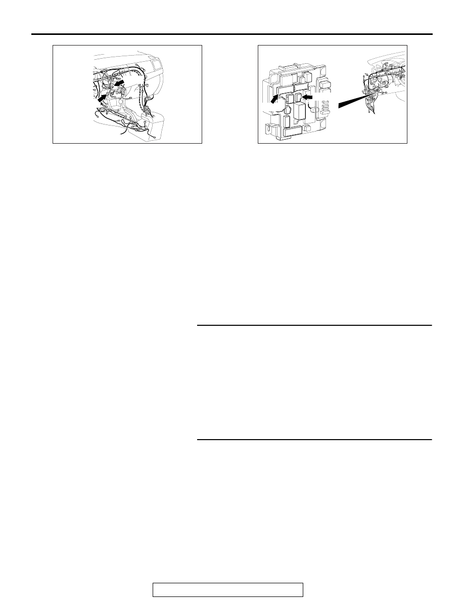
AC708951BF
C-109
C-124
Connectors: C-109, C-124
AC708972BA
Connectors: C-307, C-317
ETACS-ECU
C-307 (B)
C-317