Mitsubishi Evolution X. Manual - part 858


  Index      Mitsubishi     Mitsubishi Evolution X - service repair manual 2008 year


Search            


Content   ..  856  857  858  859   ..


Mitsubishi Evolution X. Manual - part 858


MB991006

ON-VEHICLE SERVICE

TSB Revision

FRONT SUSPENSION

33-7

ON-VEHICLE SERVICE

FRONT WHEEL ALIGNMENT CHECK AND 
ADJUSTMENT

M1332012400267

CAUTION

After performing the front wheel alignment, perform a cali-
bration for the ASC-ECU to learn the steering wheel sensor 
neutral point. (Refer to GROUP 35C 

 On-vehicle Service, 

Steering Wheel Sensor Calibration 

P.35C-267

.)

1. Before the wheel alignment measurement, maintain the 

front suspension, the steering system, the wheel and tires in 
good condition.

2. Park the vehicle on a level surface, and position the front 

wheel in the straight-ahead position to measure the wheel 
alignment.

TOE-IN

Standard value: 0 

± 2 mm (0 ± 0.07 inch)
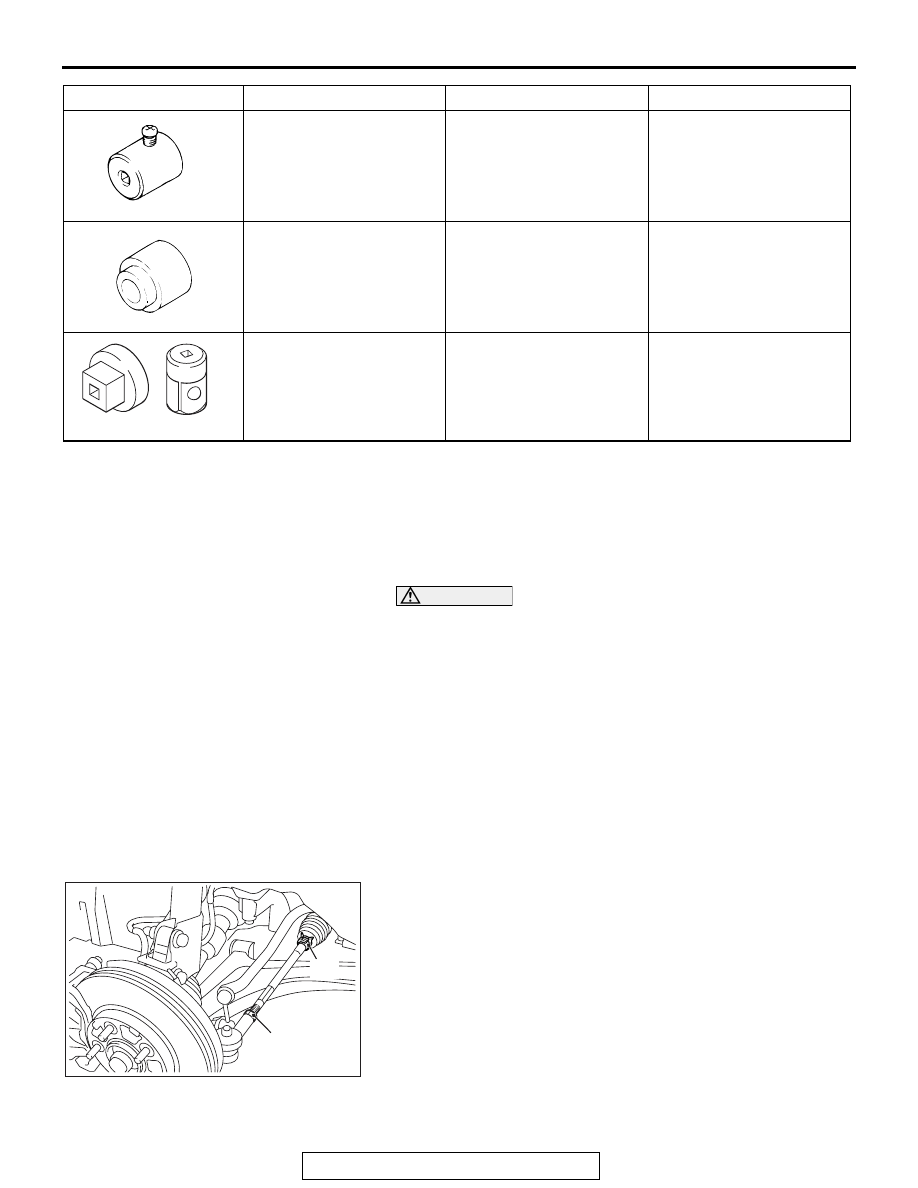
AC705438 AB

Clip

Lock nut

1. Loosen the lock nut with the tie-rod clip removed, and then 

perform the adjustment by turning the tie-rod left/right at the 
same degree in the opposite direction.
NOTE: The toe moves to the outside by turning the tie-rod 
left to the forward direction, and right to the reverse direc-
tion.

2. After adjustment, check that the steering angle is within the 

standard range using the turning radius gauge. (Refer to 
GROUP 37 

− On-vehicle Service 

P.37-14

.)

MB991006
Preload socket

MB990228-01

Lower arm ball joint 
breakaway torque check

MB990800

MB990800
Ball joint dust cover 
installer

MB990800-01or General 
service tool

Lower arm ball joint dust 
cover installation

MB990326

MB990326
Preload socket

General service tool

Ball joint turning torque 
check

Tool

Tool number and name

Supersession

Appli8cation

ON-VEHICLE SERVICE

TSB Revision

FRONT SUSPENSION

33-8

CAMBER, CASTER AND KINGPIN INCLINATION

.

CAMBER 

Standard value:


1° 00' ± 0° 30' (Left/right deviation within 30’)

.

CASTER

Standard value:


4

° 25' ± 0° 30' (Left/right deviation within 30’)

Kingpin inclination 13

° 50’ ± 1° 30’

NOTE:  Camber and caster are preset at the factory and can-
not be adjusted.

CAUTION

Do not apply the vehicle weight to the wheel bearing with 
the driveshaft nut loosened.
NOTE: 

AC704983 AB

MB991004

Tighten the wheel alignment gauge attachment (special 

tool: MB991004) to the specified torque, then perform mea-
surement.

Tightening torque: 144 

 176 N⋅ m (107  129 ft-lb)

LOWER ARM BALL JOINT LOOSENESS CHECK

M1332015000224

1. Raise the vehicle.
2. Move the lower arm assembly up and down with your hands 

to check for an excessive play in the axial direction of the 
ball joint. If there is an excessive play, replace the lower arm 
assembly.(Refer to 

P.33-15

.)

BALL JOINT DUST COVER CHECK

M1332008600741

.

LOWER ARM BALL JOINT DUST COVER CHECK

CAUTION

Do not damage the lower arm ball joint dust cover during 
maintenance.
1. Using your fingers, press the dust cover to check for a crack 

or damage.

2. If there is a crack or damage on the dust cover, replace the 

lower arm assembly. (Refer to 

P.33-15

.)

NOTE: The crack or damage on the dust cover may damage 
the ball joint.
If the dust cover is damaged during maintenance, replace 
the dust cover. (Refer to 

P.33-16

.)

.

ON-VEHICLE SERVICE

TSB Revision

FRONT SUSPENSION

33-9

STABILIZER LINK BALL JOINT DUST COVER 
CHECK

1. Using your fingers, press the dust cover to check for a crack 

or damage.

2. If there is a crack or damage on the dust cover, replace the 

stabilizer link. (Refer to 

P.33-17

.)

NOTE: The crack or damage on the dust cover may damage 
the ball joint.
If the dust cover is damaged during maintenance, replace 
the stabilizer link. (Refer to 

P.33-17

.)

STRUT ASSEMBLY

TSB Revision

FRONT SUSPENSION

33-10

STRUT ASSEMBLY

REMOVAL AND INSTALLATION

M1332001101083

CAUTION

The part indicated by * is the bolt/nut with friction coefficient stabilizer. During removal, ensure there 
is no damage, clean dust and soiling from the bearing and thread surfaces, and tighten it to the spec-
ified torque.

Post-installation Operation
Front Wheel Alignment Check and Adjustment (Refer to 

P.33-7

).

AC704992AB

1

23 ± 6 N·m
17 

± 4 ft-lb

4

6

45 ± 7 N·m
33 ± 5 ft-lb

110 ± 11 N·m
81 ± 8 ft-lb

1

5

3

13 ± 2 N·m
111 ± 22 in-lb

2

Vehicle front side

Removal steps 

1.

Harness clip and strut 
assembly connection

2.

Brake hose bracket and strut 
assembly connection

>>

A

<<

3.

Knuckle and strut connection

4.

Strut mounting nuts

5.

Strut tower bar

6.

Strut assembly

Removal steps (Continued)


Content   ..  856  857  858  859   ..