Mitsubishi Evolution X. Manual - part 812


  Index      Mitsubishi     Mitsubishi Evolution X - service repair manual 2008 year


Search            


Content   ..  810  811  812  813   ..


Mitsubishi Evolution X. Manual - part 812


DIAGNOSIS

TSB Revision

ACTIVE SKID CONTROL SYSTEM (ASC)

35C-255

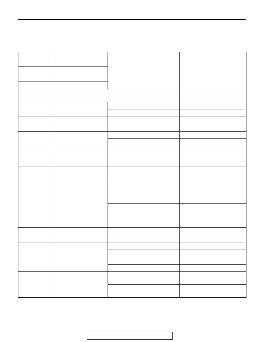
DATA LIST REFERENCE TABLE

M1355001500216

The following items of ECU input data can be read 
using the scan tool.
1. The system is normal.

Item No.

Check item

Check conditions

Normal conditions

01

FL wheel speed sensor

Perform a test run of the vehicle. The speedometer display and 

scan tool display almost agree 
with each other. <Vehicle 
stopped: Approximately 0.7 
km/h (1.1 mph)>

02

FR wheel speed sensor

03

RL wheel speed sensor

04

RR wheel speed sensor

05

Power supply voltage

System voltage (10 to 18 V 
ASC operable range)

07

Brake switch (input)

The brake pedal is depressed.

ON

The brake pedal is released.

OFF

08

Lateral G sensor (+: left 
turn, -: right turn)

Vehicle stopped (level)

-0.11 to 0.11 G

Running

-1 to 1 G

09

G sensor (+: deceleration, 
-: acceleration)

Vehicle stopped (level)

-0.11 to 0.11 G

Running

-1 to 1 G

10

Master cylinder pressure

The brake pedal is depressed.

Increases by the amount of 
the brake pedal depression.

The brake pedal is released.

-3 to 3 bar

11

Steering angle (+: left turn, 
-: right turn)

Vehicle stopped (Steering wheel 
in neutral position)

-6 to 6 deg

Running

Nearly the same as the 
steering wheel operation angle 
<-720 to 720 deg (ASC-ECU 
normal detection value)>

When removed from vehicle 
(Steering wheel sensor as a 
single unit)

Nearly the same as the 
steering wheel operation angle 
<-850 to 850 deg (Sensor 
normal value as a single unit)>

12

Yaw rate sensor (+: left 
turn, -: right turn)

Vehicle stopped (level)

-3.6 to 3.6 deg/s

Running

-100 to 100 deg/s

14

Brake switch

The brake pedal is depressed.

ON

The brake pedal is released.

OFF

15

Emission test mode

Emission test mode: ON

ON

Emission test mode: OFF

OFF

26

Brake fluid pressure 
switch

Brake fluid level is lower than the 
"LOWER" marking.

Low

Brake fluid level is higher than 
the "LOWER" marking.

Normal

DIAGNOSIS

TSB Revision

ACTIVE SKID CONTROL SYSTEM (ASC)

35C-256

28

ASC/TCL off switch

ASC OFF switch not operated 
(ASC control is available)

ON

When ASC OFF switch is 
operated (pressed shortly) (ASC 
control is prohibited)

OFF

When ASC OFF switch is 
operated (pressed and held for 
15 seconds or more) (ASC OFF 
control is prohibited by fail-safe.)

ON

45

SAS OK flag

When the learning is completed

Comp

When the learning is not 
completed

Not Comp

When the steering wheel sensor 
is faulty

SAS fail
SAS fail&Not Comp

65

Engine Speed

When the accelerator pedal is 
depressed (engine started)

The tachometer display and 
the scan tool display almost 
agree with each other.

66

Engine torque

Displays the engine torque.

67

APS sensor

Displays the accelerator pedal 
opening angle.

68

Allow ESP torque request Engine torque intervention is 

permitted

Allow

70

Target gear

The shift lever is operated

Displays the shift lever 
position.

71

Actual gear

72

Master cylinder pressure 
Offset

Master cylinder pressure sensor 
correction amount at the master 
cylinder pressure sensor 
calibration

-8 to 8 bar

73

Lateral G sensor offset

Lateral G sensor correction 
amount at G and yaw rate sensor 
calibration

-0.17 to 0.17 G

86

Ignition switch

Ignition switch is "ON" position

ON

87

Ignition switch (input)

Ignition switch is "ON" position

ON

Ignition switch is "START" 
position

START

88

Vehicle speed

Perform a test run of the vehicle. The speedometer display and 

scan tool display almost agree 
with each other.

91

Brake pressure sensor

The brake pedal is depressed.

Pressed

The brake pedal is released.

Not pressed

96

G sensor offset

Longitudinal G sensor correction 
amount at G and yaw rate sensor 
calibration

-0.3 to 0.3 G

97

Yaw rate sensor offset

Yaw rate sensor correction 
amount at G and yaw rate sensor 
calibration

-6.0 to 6.0 deg/s

Item No.

Check item

Check conditions

Normal conditions

DIAGNOSIS

TSB Revision

ACTIVE SKID CONTROL SYSTEM (ASC)

35C-257

2. System shutdown by ECU


While ASC-ECU is disabled by the diagnostic 
function, the scan tool displayed data is different 
from the actual measurement.

ACTUATOR TEST REFERENCE TABLE

M1355001600172

Using scan tool, the following actuators can be forc-
ibly operated:
NOTE: 

.

ABS, TCL, and skid control are operated by 
ASC-ECU.

When ASC-ECU is disabled due to the fail-safe 
function, the actuator test cannot be performed.

The actuator test can be performed only when 
the vehicle is stationary.

While the actuator test is performed, the ABS 
warning light flashes at a rate of 2 Hz.

After the actuator test has been performed, the 
brake warning light, ABS warning light, ASC ON 
indicator light, and ASC OFF indicator light illumi-
nate until the ignition switch is turned to ON again 
or the communication between scan tool and 
ASC-ECU is terminated.

.

105

Power supply voltage (input)

System voltage (10 to 18 V 
ASC operable range)

120

Parking brake switch 
(input)

When the parking brake lever is 
pulled up.

ON

When the parking brake lever is 
released.

OFF

128

ASC/TCL off switch

When the ASC OFF switch is 
pressed.

ON

When the ASC OFF switch is not 
pressed.

OFF

129

FL wheel cylinder 
pressure

The brake pedal is depressed.

Increases by the amount of 
the brake pedal depression.

The brake pedal is released.

-3 to 3 bar

130

FR wheel cylinder 
pressure

The brake pedal is depressed.

Increases by the amount of 
the brake pedal depression.

The brake pedal is released.

-3 to 3 bar

131

RL wheel cylinder 
pressure

The brake pedal is depressed.

Increases by the amount of 
the brake pedal depression.

The brake pedal is released.

-3 to 3 bar

132

RR wheel cylinder 
pressure

The brake pedal is depressed.

Increases by the amount of 
the brake pedal depression.

The brake pedal is released.

-3 to 3 bar

133

FL wheel cylinder pres. 
offset

Wheel cylinder fluid pressure 
sensor correction amount

-8 to 8 bar

134

FR wheel cylinder pres. 
offset

135

RL wheel cylinder pres. 
offset

136

RR wheel cylinder pres. 
offset

Item No.

Check item

Check conditions

Normal conditions

DIAGNOSIS

TSB Revision

ACTIVE SKID CONTROL SYSTEM (ASC)

35C-258

Actuator test specifications

.

Operation pattern of items 01 to 08 

Item No.

Check item

Driven component

01

FL wheel ABS drive

Solenoid valve for the corresponding 
channel of the hydraulic unit and pump 
motor (simplified inspection mode)

02

FR wheel ABS drive

03

RL wheel ABS drive

04

RR wheel ABS drive

05

FL wheel TCL drive

06

FR wheel TCL drive

07

RL wheel TCL drive

08

RR wheel TCL drive

09

Engine TCL drive

Outputs the engine torque control signal 
(engine torque = 0 N

⋅ m) to the engine 

ECU for three seconds.

AC400776

1seconds

2 seconds

Approx. 0.05
seconds

Approx. 0.01
seconds

AB

End

Scan tool actuator test
(Item No.05, 06, 07, 08) start

End

Increase in pressure

Steady pressure

Reduction in pressure

Increase in pressure

Steady pressure

Reduction in pressure

Drive

Stop

Cut valve,
Suction valve
(TCL/Skid control)

Solenoid valve
(ABS)

Pump motor

Scan tool actuator test
(Item No.01, 02, 03, 04) start


Content   ..  810  811  812  813   ..