Mitsubishi Evolution X. Manual - part 787


  Index      Mitsubishi     Mitsubishi Evolution X - service repair manual 2008 year


Search            


Content   ..  785  786  787  788   ..


Mitsubishi Evolution X. Manual - part 787


DIAGNOSIS

TSB Revision

ACTIVE SKID CONTROL SYSTEM (ASC)

35C-155

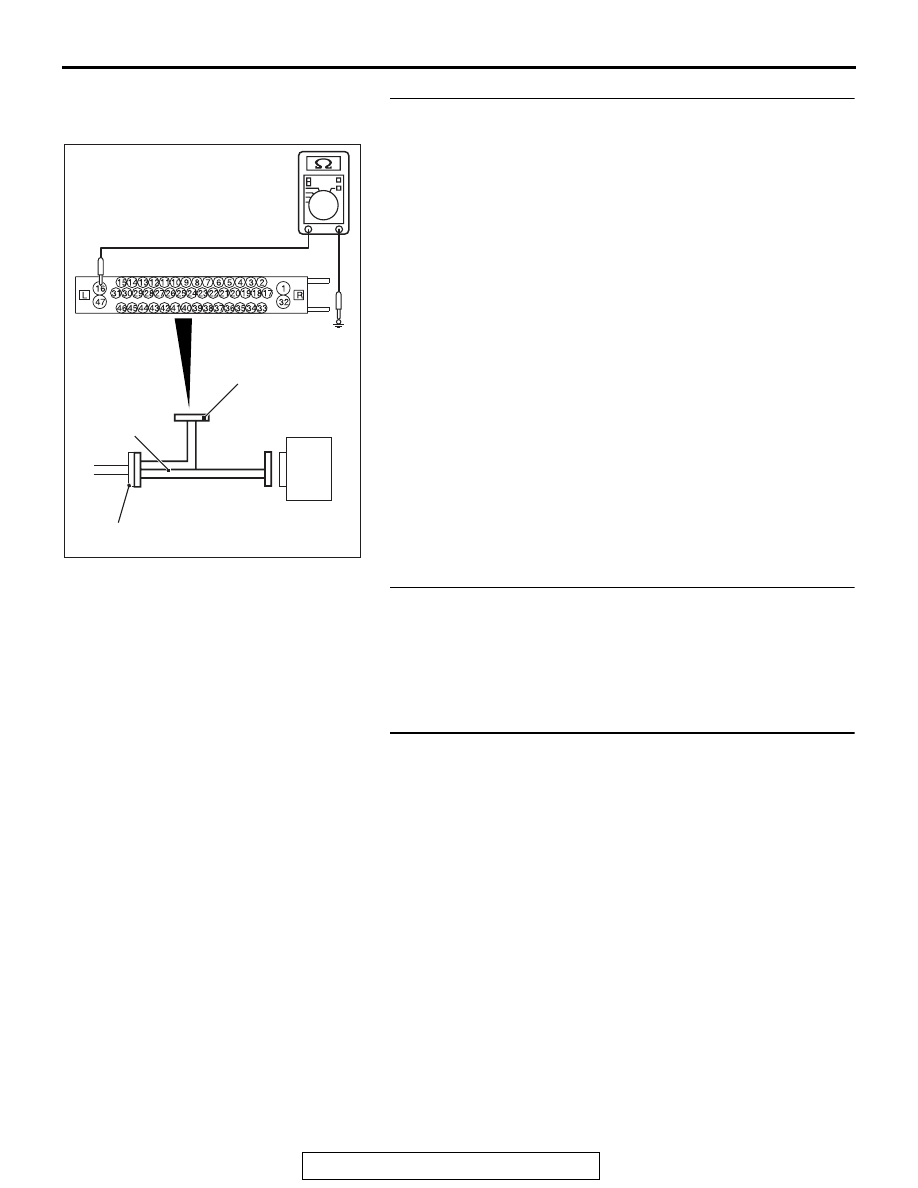
STEP 15. Resistance measurement at A-05 ASC-ECU 
connector
(1) Disconnect the connector, connect the ABS check harness 

(Special tool: MB991997) to the wiring harness-side 
connector, and measure the voltage at the special tool 
connector side.
NOTE: Do not connect the special tool to ASC-ECU.

(2) Measure the resistance between the terminal No. 16 and 

the body ground as well as between the terminal No. 47 
and the body ground.

OK: Continuity exists (2 

 or less)

Q: Is the check result normal?

YES : Go to Step 16.
NO  :  Repair the wiring harness.

STEP 16. Check whether the DTC is reset.
Q: Is DTC C2101 set?

YES : Replace the hydraulic unit (incorporates in 

ASC-ECU).(Refer to 

P.35C-272

.) Then go to Step 17.

NO :  Intermittent malfunction. (Refer to GROUP 00 

− How 

to Cope with Intermittent Malfunction 

P.00-15

.)

STEP 17. Check whether the DTC is reset.
Q: Is DTC C2101 set?

YES : Return to Step 1.
NO :  The procedure is complete.

AC400817CO

ASC-ECU

MB991997

A-05 ASC-ECU 
harness connector

Check harness

DIAGNOSIS

TSB Revision

ACTIVE SKID CONTROL SYSTEM (ASC)

35C-156

DTC C1395: Brake fluid filling not completed

CAUTION

• If there is any problem in the CAN bus lines, an incor-

rect diagnostic trouble code may be set. Prior to this 
diagnosis, diagnose the CAN bus lines.

• Whenever the ECU is replaced, ensure that the CAN 

bus lines are normal.

• When the hydraulic unit (integrated with ASC-ECU) is 

replaced, always perform the calibration of steering 
wheel sensor, G and yaw rate sensor, brake fluid pres-
sure sensor, cut valve, and inlet valve.(Refer to 

P.35C-266

P.35C-267

P.35C-268

, and 

P.35C-269

.)

.

DTC SET CONDITIONS

This diagnostic trouble code is set when the brake fluid is not 
filled in the hydraulic unit.

.

PROBABLE CAUSES

• Different hydraulic unit (For delivery to factory)

• ASC-ECU malfunction

DIAGNOSIS

Required Special Tools:

• MB991958 Scan Tool (M.U.T.-III Sub Assembly)

• MB991824: V.C.I.

• MB991827 M.U.T.-III USB Cable

• MB991910 M.U.T.-III Main Harness A

STEP 1. Using scan tool MB991958, diagnose the CAN bus 
lines.
Using scan tool MB991958, diagnose the CAN bus lines.
Q: Is the check result normal?

YES : Go to Step 2.
NO :  Repair the CAN bus lines. (Refer to GROUP 54C 

− 

Troubleshooting 

P.54C-14

.) After repairing the CAN 

bus line, go to Step 2.

STEP 2. DTC recheck after repairing the CAN bus line
Q: Is DTC C1395 set?

YES : Replace the hydraulic unit (incorporates in 

ASC-ECU).(Refer to 

P.35C-272

.)

NO :  The procedure is complete.

DIAGNOSIS

TSB Revision

ACTIVE SKID CONTROL SYSTEM (ASC)

35C-157

DTC C121C: Torque request signal rejection

CAUTION

• If there is any problem in the CAN bus lines, an incor-

rect diagnostic trouble code may be set. Prior to this 
diagnosis, diagnose the CAN bus lines.

• Whenever the ECU is replaced, ensure that the CAN 

bus lines are normal.

• When the hydraulic unit (integrated with ASC-ECU) is 

replaced, always perform the calibration of steering 
wheel sensor, G and yaw rate sensor, brake fluid pres-
sure sensor, cut valve, and inlet valve.(Refer to 

P.35C-266

P.35C-267

P.35C-268

, and 

P.35C-269

.)

.

CIRCUIT OPERATION

ASC-ECU sends the signal to the engine control module as 
necessary to decrease the engine output for ASC system oper-
ation.

.

DTC SET CONDITIONS

This diagnostic trouble code is set when the output decrease 
request is rejected by the engine control module.

.

PROBABLE CAUSES

• Wrong coding

• Engine ECU malfunction

• ASC-ECU malfunction

• External noise interference

DIAGNOSIS

Required Special Tools:

• MB991958 Scan Tool (M.U.T.-III Sub Assembly)

• MB991824: Vehicle Communication Interface (V.C.I.)

• MB991827 M.U.T.-III USB Cable

• MB991910 M.U.T.-III Main Harness A

STEP 1. Using scan tool MB991958, diagnose the CAN bus 
lines.
Using scan tool MB991958, diagnose the CAN bus lines.
Q: Is the check result normal?

YES : Go to Step 3.
NO :  Repair the CAN bus lines. (Refer to GROUP 54C 

− 

Troubleshooting 

P.54C-14

.) After repairing the CAN 

bus line, go to Step 2.

STEP 2. DTC recheck after repairing the CAN bus line
Q: Is DTC C121C set?

YES : Go to Step 3.
NO :  The procedure is complete.

DIAGNOSIS

TSB Revision

ACTIVE SKID CONTROL SYSTEM (ASC)

35C-158

STEP 3. M.U.T.-III other system diagnostic trouble code
Using scan tool MB991958, check if a diagnostic trouble code 
is set in the engine control module. (Refer to GROUP 13A 

− 

Troubleshooting 

P.13A-44

.)

Q: Is any DTC set?

YES : Troubleshoot the diagnostic trouble code of engine 

control module. (Refer to GROUP 13A 

− 

Troubleshooting 

P.13A-44

.)

NO :  Go to Step 4.

STEP 4. Scan tool service data
Check the following service data. (Refer to 

P.35C-255

.)

• Item 68: Allow ESP torque request

Q: Is the check result normal?

YES : Go to Step 5.
NO :  Replace the engine control module. (Refer to GROUP 

13A 

− Engine Control Module 

P.13A-920

.) Then go to 

Step 5.

STEP 5. Check whether the DTC is reset.
Q: Is DTC C121C set?

YES : Replace the hydraulic unit (incorporates in 

ASC-ECU).(Refer to 

P.35C-272

.) Then go to Step 6.

NO :  Intermittent malfunction. (Refer to GROUP 00 

− How 

to Cope with Intermittent Malfunction 

P.00-15

.)

STEP 6. Check whether the DTC is reset.
Q: Is DTC C121C set?

YES : Return to Step 1.
NO :  The procedure is complete.


Content   ..  785  786  787  788   ..