Mitsubishi Evolution X. Manual - part 731


  Index      Mitsubishi     Mitsubishi Evolution X - service repair manual 2008 year


Search            


Content   ..  729  730  731  732   ..


Mitsubishi Evolution X. Manual - part 731


POST-COLLISION DIAGNOSIS

TSB Revision

SUPPLEMENTAL RESTRAINT SYSTEM (SRS)

52B-371

POST-COLLISION DIAGNOSIS

M1524001101639

To inspect and service the SRS after a collision (whether or not 
the air bags have deployed), perform the following steps.

SRS-ECU MEMORY CHECK

Required Special Tool:

•  MB991958: Scan Tool (M.U.T.-III Sub Assembly)

• MB991824:Vehicle Communication Interface (V.C.I.)

• MB991827:M.U.T.-III USB Cable

• MB991910:M.U.T.-III Main Harness A (Vehicles with 

CAN Communication System)

CAUTION

To prevent damage to scan tool MB991958, always turn the 
ignition switch to the "LOCK" (OFF) position before con-
necting or disconnecting scan tool MB991958.
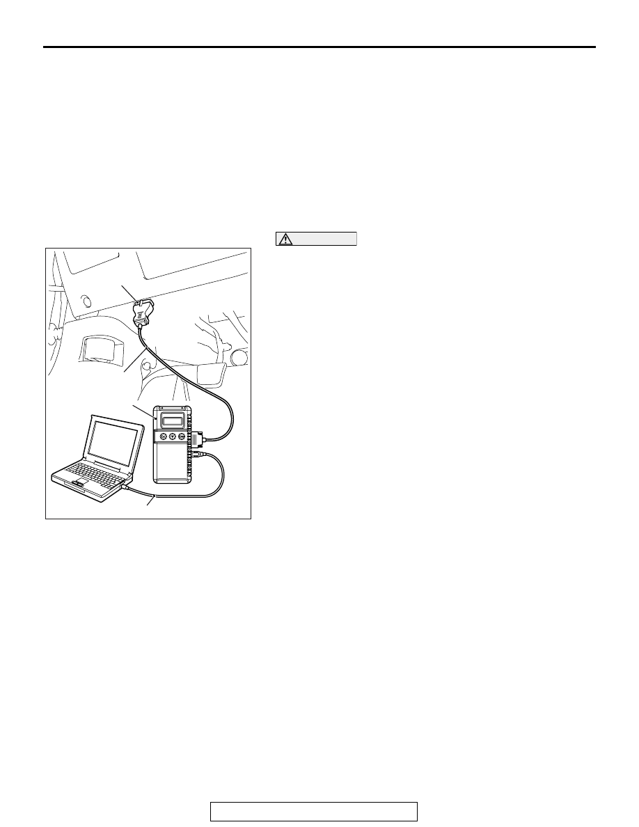
1. Connect scan tool MB991958 to the data link connector 

(16-pin).

2. Read (and write down) all displayed diagnostic trouble 

codes (Refer to SRS-ECU 

P.52B-31

, Occupant 

classification-ECU 

P.52B-297

).

NOTE: If the battery power supply has been disconnected or 
disrupted by the collision, scan tool MB991958 cannot com-
municate with the SRS-ECU. Check the battery, then check 
and, if necessary, repair the front wiring harness and the 
instrument panel wiring harness before proceeding.

3. Read the data list (fault duration and how many times 

memories are erased), using scan tool MB991958 (Refer to 

P.52B-367

).

4. Erase the diagnostic trouble codes, and then turn the 

ignition switch to the LOCK (OFF) position.

5. Wait for at least one second, and then turn the ignition 

switch to the ON position again.

6. After waiting 15 seconds or more, note all displayed 

diagnostic trouble codes (Refer to SRS-ECU 

P.52B-31

Occupant classification-ECU 

P.52B-297

).

AC608435

Data link connector

MB991827

MB991824

MB991910

AB

POST-COLLISION DIAGNOSIS

TSB Revision

SUPPLEMENTAL RESTRAINT SYSTEM (SRS)

52B-372

REPAIR PROCEDURE

.

WHEN FRONT AIR BAGS DEPLOY IN A COLLI-
SION.

1. Replace the following parts with new ones:

• Front impact sensors (Refer to 

P.52B-380

).

• SRS-ECU (Refer to 

P.52B-383

).

• Driver’s air bag modules (Refer to 

P.52B-386

).

• Passenger’s (front) air bag modules (Refer to 

P.52B-393

).

• Knee air bag module (Refer to 

P.52B-398

).

• Seat belt with pre-tensioner (Refer to 

P.52B-413

).

• Instrument panel assembly (Refer to GROUP 52A, Instru-

ment Panel Assembly 

P.52A-2

).

• Slide adjuster (RH) (Refer to GROUP 52A, Front Seat 

Assembly 

P.52A-24

).

2. Check the following parts and replace if there are any 

malfunctions:

• Clock spring (Refer to 

P.52B-386

).

• Seat slide sensor 

• Seat belt switch (Refer to GROUP 52A, Front Seat Belt, 

Inspection 

P.52A-29

).

• Steering wheel, steering column shaft assembly

(1) Check the wiring harness (built into the steering wheel) 

and connectors for damage, and terminals for 
deformation.

(2) Install the air bag module to check fit and alignment with 

the steering wheel.

(3) Check the steering wheel for noise, binding or difficult 

operation and excessive free play.

(4) Check the steering column shaft shock absorbing 

mechanism (Refer to GROUP 37, On-Vehicle Service 

− 

Steering Column Shaft Assembly Shock Absorbing 
Mechanism Check).

3. Check the wiring harnesses for binding, the connectors for 

damage, poor connections, and the terminals for 
deformation (Refer to 

P.52B-25

).

.

WHEN SIDE AIR BAGS DEPLOY IN A COLLISION.

1. Replace the following parts with new ones:

• SRS-ECU (Refer to 

P.52B-383

).

• Side impact sensors (Refer to 

P.52B-402

).

• Front seatback (Refer to GROUP 52A, Front Seat Assem-

bly 

P.52A-24

).

• Slide adjuster (RH) (Refer to GROUP 52A, Front Seat 

Assembly 

P.52A-24

).

2. Check the wiring harnesses for binding, the connectors for 

damage, poor connections, and the terminals for 
deformation (Refer to 

P.52B-25

).

.

POST-COLLISION DIAGNOSIS

TSB Revision

SUPPLEMENTAL RESTRAINT SYSTEM (SRS)

52B-373

WHEN AIR BAGS DO NOT DEPLOY IN 
LOW-SPEED COLLISION.

Check the SRS components. If the SRS components are show-
ing any visible damage such as dents, cracks, or deformation, 
replace them with new ones. Concerning parts removed for 
inspection, replacement with new parts and cautionary points 
for working, refer to appropriate INDIVIDUAL COMPONENT 
SERVICE 

P.52B-377

.

.

FRONT IMPACT SENSOR

1. Check the front end upper bar for distortion and rust.
2. Check the front impact sensor for dents, cracks, deformation 

or rust.

3. Check the front impact sensor wiring harness for binding, 

check the connector for damage, and check the terminals 
for deformation.

NOTE:  The illustration shows the side impact sensor (LH). The 
position of the side impact sensor (RH) is symmetrical to this.

.

SRS-ECU

1. Check the SRS-ECU case and brackets for dents, cracks or 

deformation.

2. Check the connector for damage, and the terminals for 

deformation.

3. Check the installation of the SRS-ECU and its bracket.

.

AC608583

Front impact sensor

AB

AC605641

                 AC

SRS-ECU

Rear heater
duct (LH)

POST-COLLISION DIAGNOSIS

TSB Revision

SUPPLEMENTAL RESTRAINT SYSTEM (SRS)

52B-374

AIR BAG MODULES

1. Check the pad cover for dents, cracks or deformation.
2. Check the connector for damage, terminal deformities, and 

the harness for binding.

3. Check the air bag inflator case for dents, cracks or 

deformities.

4. Install the air bag module (driver's side) to the steering 

wheel to check installation or alignment with the steering 
wheel.

5. Install the air bag module (front passenger's side) to the 

instrument panel and front deck crossmember to check 
installation or alignment.

.

FRONT SEATBACK ASSEMBLY (SIDE-AIR BAG 
MODULE)

1. Check the air bag module deployment section for dents or 

deformation.

2. Check that there is no connector damage, bent terminals or 

harness crimping.

.

AC709173

Squib 
connectors

Inflator

Squib connectors

Inflator

<Driver's side>

<Passenger's side>

AB

<Knee air bag module>

Squib 
connectors

Inflator

AC707634 AC

Side-airbag module 
deployment section


Content   ..  729  730  731  732   ..