Mitsubishi Evolution X. Manual - part 723


  Index      Mitsubishi     Mitsubishi Evolution X - service repair manual 2008 year


Search            


Content   ..  721  722  723  724   ..


Mitsubishi Evolution X. Manual - part 723


SRS AIR BAG DIAGNOSIS

TSB Revision

SUPPLEMENTAL RESTRAINT SYSTEM (SRS)

52B-339

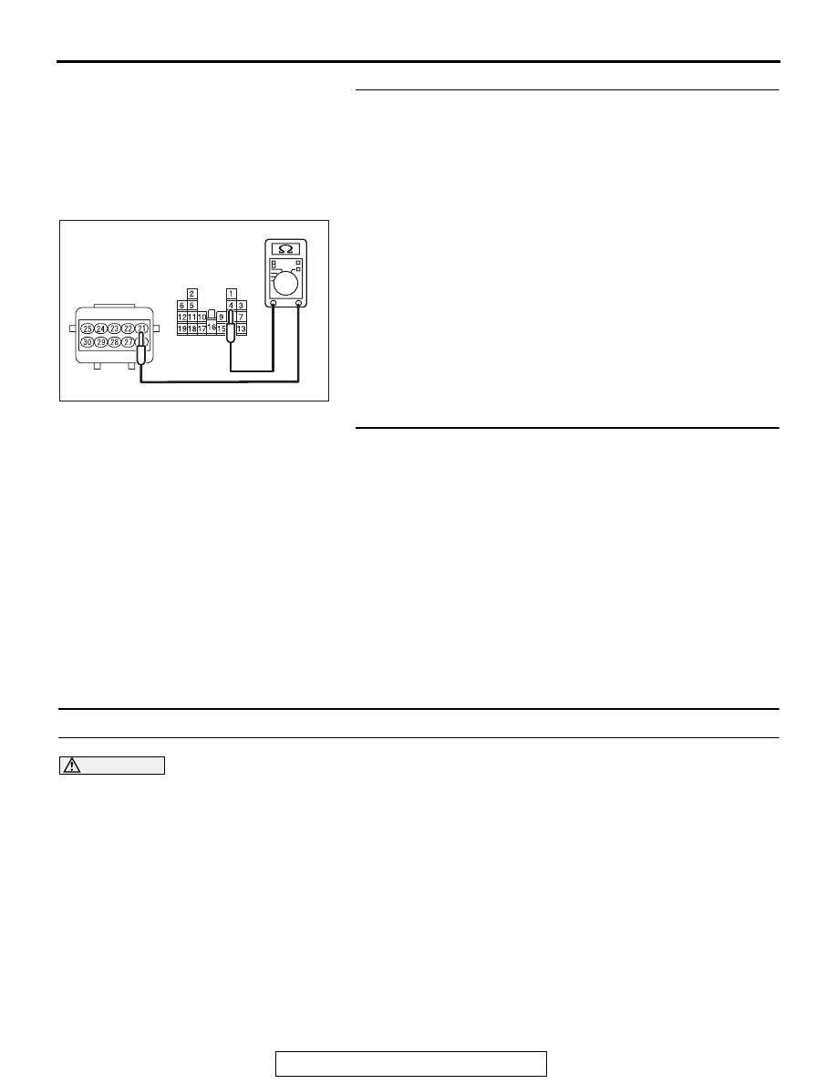
STEP 9. Check the harness for open circuit between 
occupant classification-ECU connector D-39-2 (terminal 
No.21) and the ETACS-ECU connector C-315 (terminal 
No.4).
(1) Disconnect the negative battery terminal.
(2) Disconnect occupant classification-ECU connector D-39-2.
(3) Disconnect the ETACS-ECU connector C-315.
(4) Check for continuity between the following terminals. It 

should be less than 2 ohms.

• occupant classification-ECU connector D-39-2 (terminal 

No.21) and the ETACS-ECU connector C-315 (terminal 
No.4)

Q: Does continuity exist?

YES : Go to Step 10.
NO :  Repair the harness wire between occupant 

classification-ECU connector D-39-2 and the 
ETACS-ECU connector C-315.

STEP 10. Recheck for diagnostic trouble code.
Check again if the DTC is set.
(1) Erase the DTC.
(2) Turn the ignition switch to the "ON" position.
(3) Check if the DTC is set.
(4) Turn the ignition switch to the "LOCK" (OFF) position.
Q: Is DTC B210D or B210E set?

YES : Replace the slide adjuster (RH) (Refer to GROUP 

52A, Front Seat Assembly 

P.52A-24

).

NO :  There is an intermittent malfunction such as poor 

engaged connector(s) or open circuit (Refer to 
GROUP 00, How to Cope with Intermittent 
Malfunction 

P.00-15

).

DTC B2206: Chassis number does not match

CAUTION

If DTC B2206 is set in the occupant classifica-
tion-ECU, always diagnose the CAN bus line.

.

TROUBLE JUDGMENT

If the registered chassis number is different from the 
chassis number transmitted on the CAN bus lines, 
the occupant classification-ECU sets the DTC 
B2206.

.

JUDGMENT CRITERIA

If the chassis number registered to occupant classifi-
cation-ECU and the chassis number on CAN bus 
lines do not match, the occupant classification-ECU 
determines that a problem has occurred.

.

TROUBLESHOOTING HINTS

• Chassis number not written

• The occupant classification-ECU may be defec-

tive.

• The CAN bus line may be defective.

AC608812

C-315 
Harness side 
connector 
(front view)

HB

D-39-2 
Harness side 
connector 
(front view)

SRS AIR BAG DIAGNOSIS

TSB Revision

SUPPLEMENTAL RESTRAINT SYSTEM (SRS)

52B-340

DIAGNOSIS

Required Special Tools:

• MB991958: Scan Tool (M.U.T.-III Sub Assembly)

• MB991824: Vehicle Communication Interface (V.C.I.)

• MB991827: M.U.T.-III USB Cable

• MB991910: M.U.T.-III Main Harness A (Vehicles with 

CAN communication system)

STEP 1. Using scan tool MB991958, diagnose the CAN bus 
line.

CAUTION

To prevent damage to scan tool MB991958, always turn the 
ignition switch to the "LOCK" (OFF) position before con-
necting or disconnecting scan tool MB991958.
(1) Connect scan tool MB991958. Refer to "How to connect the 

Scan Tool (M.U.T.-III) 

P.52B-28

."

(2) Turn the ignition switch to the "ON" position.
(3) Diagnose the CAN bus line.
(4) Turn the ignition switch to the "LOCK" (OFF) position.
Q: Is the CAN bus line found to be normal?

YES : Accuracy check is performed. Then go to Step 2.
NO :  Repair the CAN bus line (Refer to GROUP 54C, 

Diagnosis 

P.54C-14

).

STEP 2. Recheck for diagnostic trouble code.
Check again if the DTC is set to the occupant classifica-
tion-ECU.
(1) Zero calibration of occupant classification-ECU.
(2) Erase the DTC.
(3) Turn the ignition switch from "LOCK" (OFF) position to "ON" 

position.

(4) Check if DTC is set.
(5) Turn the ignition switch to the "LOCK" (OFF) position.
Q: Is the DTC set?

YES : Replace the slide adjuster (RH) (Refer to GROUP 

52A, Front Seat Assembly 

P.52A-24

).

NO :  There is an intermittent malfunction such as poor 

engaged connector(s) or open circuit (Refer to 
GROUP 00, How to Cope with Intermittent 
Malfunction 

P.00-15

).

AC608435

Data link connector

MB991827

MB991824

MB991910

AB

SRS AIR BAG DIAGNOSIS

TSB Revision

SUPPLEMENTAL RESTRAINT SYSTEM (SRS)

52B-341

DTC U0020: CAN-B Bus Off Performance


DTC U0021: CAN-B Bus (HI) Circuit Open


DTC U0022: CAN-B Bus (HI) Shorted to Circuit Ground


DTC U0023: CAN-B Bus (HI) Shorted to Circuit Power Supply


DTC U0024: CAN-B Bus (LO) Circuit Open


DTC U0025: CAN-B Bus (LO) Shorted to Circuit Ground


DTC U0026: CAN-B Bus (LO) Shorted to Circuit Power Supply

CAUTION

• If the DTC U0020, U0021, U0022, U0023, 

U0024, U0025, U0026 is set in the occupant 
classification-ECU, always diagnose the CAN 
main bus lines.

• When replacing the ECU, always check that 

the communication circuit is normal.

.

DIAGNOSTIC FUNCTION

If the CAN-B circuit malfunction, the occupant classi-
fication-ECU sets the DTC U0020, U0021, U0022, 
U0023, U0024, U0025, U0026.

.

JUDGMENT CRITERIA

Because of the CAN-B bus circuit malfunction, if 
occupant classification-ECU becomes unable to per-
form the normal data transmission, occupant classifi-
cation-ECU determines that an abnormality is 
present.

.

TROUBLESHOOTING HINTS

The CAN bus line may be defective

DIAGNOSIS

Required Special Tools:

• MB991958: Scan Tool (M.U.T.-III Sub Assembly)

• MB991824: Vehicles Communication Interface (V.C.I.)

• MB991827: M.U.T.-III USB Cable

• MB991910: M.U.T.-III Main Harness A (Vehicles with 

CAN communication system)

SRS AIR BAG DIAGNOSIS

TSB Revision

SUPPLEMENTAL RESTRAINT SYSTEM (SRS)

52B-342

STEP 1. Recheck for diagnostic trouble code.
Check again if the DTC is set to the occupant classifica-
tion-ECU.

CAUTION

To prevent damage to scan tool MB991958, always turn the 
ignition switch to the "LOCK" (OFF) position before con-
necting or disconnecting scan tool MB991958.
(1) Connect scan tool MB991958. Refer to "How to connect the 

scan tool 

P.52B-28

."

(2) Turn the ignition switch to the "ON" position.
(3) Check if DTC is set.
(4) Turn the ignition switch to the "LOCK" (OFF) position.
Q: Is the DTC set?

YES : Go to Step 2.
NO :  There is an intermittent malfunction such as poor 

engaged connector(s) or open circuit (Refer to 
GROUP 00, How to Cope with Intermittent 
Malfunction 

P.00-15

).

STEP 2. Using scan tool MB991958, diagnose the CAN bus 
line.
(1) Turn the ignition switch to the "ON" position.
(2) Diagnose the CAN bus line.
(3) Turn the ignition switch to the "LOCK" (OFF) position.
Q: Is the CAN bus line found to be normal?

YES : There is an intermittent malfunction such as poor 

engaged connector(s) or open circuit (Refer to 
GROUP 00, How to Cope with Intermittent 
Malfunction 

P.00-15

).

NO :  Repair the CAN bus line (Refer to GROUP 54C, 

Diagnosis 

P.54C-14

).

AC608435

Data link connector

MB991827

MB991824

MB991910

AB


Content   ..  721  722  723  724   ..