Mitsubishi Evolution X. Manual - part 716


  Index      Mitsubishi     Mitsubishi Evolution X - service repair manual 2008 year


Search            


Content   ..  714  715  716  717   ..


Mitsubishi Evolution X. Manual - part 716


SRS AIR BAG DIAGNOSIS

TSB Revision

SUPPLEMENTAL RESTRAINT SYSTEM (SRS)

52B-311

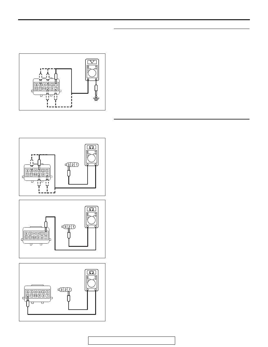
STEP 3. Measure the voltage at occupant 
classification-ECU connector D-39-1.
(1) Disconnect the connector D-39-1.
(2) Turn the ignition switch to the "ON" position.
(3) Measure the voltage between terminals 1, 3, 5, 7, 9 and 

body ground.
Voltage should measure 0 volts.

Q: Is the measured voltage with in the specified range?

YES : Go to Step 4.
NO :  Repair the wiring harness between the occupant 

classification-ECU connector D-39-1 terminals 1, 3, 5, 
7, 9 and the body ground. Then go to Step 5.

STEP 4. Check the harness open circuit between occupant 
classification-ECU connector D-39-1 and weight sensor 
connector D-39-3, D-39-4, D-39-5 or D-39-6.
(1) Disconnect occupant classification-ECU connector D-39-1 

and weight sensor connector D-39-3, D-39-4, D-39-5 or 
D-39-6.

(2) Check for continuity between the following terminals.

It should be less than 2 ohms.

• Occupant classification-ECU connector D-39-1 (terminal 

No.3) and the weight sensor connector D-39-3 (terminal 
No.3)

• Occupant classification-ECU connector D-39-1 (terminal 

No.5) and the weight sensor connector D-39-4 (terminal 
No.3)

• Occupant classification-ECU connector D-39-1 (terminal 

No.7) and the weight sensor connector D-39-6 (terminal 
No.3)

• Occupant classification-ECU connector D-39-1 (terminal 

No.9) and the weight sensor connector D-39-5 (terminal 
No.3)

• Occupant classification-ECU connector D-39-1 (terminal 

No.1) and the weight sensor connector D-39-3, D-39-4, 
D-39-5 and D-39-6 (terminal No.2)

• Occupant classification-ECU connector D-39-1 (terminal 

No.12) and weight sensor connector D-39-3, D-39-4, 
D-39-5 and D-39-6 (terminal No.1)

Q: Does continuity exist?

YES : Erase the diagnostic trouble code memory, and check 

the diagnostic trouble code. If DTC B1B7A, B1B7F, 
B1B84 or B1B89 set, replace the slide adjuster (RH).

NO :  Repair the harness wires between occupant 

classification-ECU connector D-39-1 and weight 
sensor connector D-39-3, D-39-4, D-39-5 and D-39-6. 
Then go to Step 5.

AC608813 BM

D-39-1 Harness side 
connector (front view)

AC608812GR

D-39-1 Harness side 
connector (front view)

D-39-3,  D-39-4, 
D-39-5, D-39-6
Harness side 
connector 
(front view)

AC608812GS

D-39-1 Harness side 
connector (front view)

D-39-3,  D-39-4, 
D-39-5, D-39-6
Harness side 
connector 
(front view)

AC608812GT

D-39-1 Harness side 
connector (front view)

D-39-3,  D-39-4, 
D-39-5, D-39-6
Harness side 
connector 
(front view)

SRS AIR BAG DIAGNOSIS

TSB Revision

SUPPLEMENTAL RESTRAINT SYSTEM (SRS)

52B-312

STEP 5. Recheck for diagnostic trouble code.
Check again if the DTC is set.
(1) Erase the DTC.
(2) Turn the ignition switch to the "ON" position.
(3) Check if the DTC is set.
(4) Turn the ignition switch to the "LOCK" (OFF) position.
Q: Is DTCs B1B7A, B1B7F, B1B84, B1B89 set?

YES : Replace the slide adjuster (RH) (Refer to GROUP 

52A, Front Seat Assembly 

P.52A-24

).

NO :  There is an intermittent malfunction such as poor 

engaged connector(s) or open circuit (Refer to 
GROUP 00, How to Cope with Intermittent 
Malfunction 

P.00-15

).

DTC B1B8C: Seat Slide Sensor Circuit Performance

OCCUPANT 
CLASSIFICATION-
ECU

HALL IC

SEAT SLIDE 
SENSOR (LH)

FRONT SEAT 
ASSEMBLY (RH)

Seat Slide Sensor Circuit

SRS AIR BAG DIAGNOSIS

TSB Revision

SUPPLEMENTAL RESTRAINT SYSTEM (SRS)

52B-313

CAUTION

If DTC B1B8C is set in the occupant classifica-
tion-ECU, always diagnose the CAN main bus 
lines.

.

CIRCUIT OPERATION

• The seat slide sensor sets the current value Hi or 

Low determined by the seat position.

• The occupant classification-ECU determines the 

seat position according to the current value from 
the seat slide sensor.

.

DTC SET CONDITION

The DTC is set when the seat slide sensor output 
current is not within the specified range.

.

TROUBLESHOOTING HINTS

• The seat slide sensor may be defective.

• The wiring harness or connectors may have 

loose, corroded, or damaged terminals, or termi-
nals pushed back in the connector

DIAGNOSIS

Required Special Tools:

• MB991958 Scan Tool (M.U.T.-III Sub Assembly)

• MB991824: Vehicle Communication Interface (V.C.I.)

• MB991827 M.U.T.-III USB Cable

• MB991910 M.U.T.-III Main Harness A (Vehicles with 

CAN communication system)

AC708954 AM

D-32 (GR)

Connectors: D-32, D-39, D-39-2

D-39, D-39-2

SRS AIR BAG DIAGNOSIS

TSB Revision

SUPPLEMENTAL RESTRAINT SYSTEM (SRS)

52B-314

STEP 1. Using scan tool MB991958, diagnose the CAN bus 
line.

CAUTION

To prevent damage to scan tool MB991958, always turn the 
ignition switch to the "LOCK" (OFF) position before con-
necting or disconnecting scan tool MB991958.
(1) Connect scan tool MB991958. Refer to "How to connect the 

scan tool 

P.52B-28

."

(2) Turn the ignition switch to the "ON" position.
(3) Diagnose the CAN bus line.
(4) Turn the ignition switch to the "LOCK" (OFF) position.
Q: Is the CAN bus line found to be normal?

YES : Go to Step 2.
NO :  Repair the CAN bus line (Refer to GROUP 54C, 

Diagnosis 

P.54C-14

).

STEP 2. Recheck for diagnostic trouble code.
Check again if the DTC is set.
(1) Erase the DTC.
(2) Turn the ignition switch to the "ON" position.
(3) Check if the DTC is set.
(4) Turn the ignition switch to the "LOCK" (OFF) position.
Q: Is the DTC set?

YES : Go to Step 3.
NO :  There is an intermittent malfunction such as poor 

engaged connector(s) or open circuit (Refer to 
GROUP 00, How to Cope with Intermittent 
Malfunction 

P.00-15

).

STEP 3. Check the occupant classification-ECU connector 
D-39-2, front seat assembly D-39 and seat slide sensor 
D-32 for loose, corroded or damaged terminals, or 
terminals pushed back in the connector.
Q: Is the occupant classification-ECU connector D-39-2, 

front seat assembly D-39 and seat slide sensor D-32 in 
good condition?
YES : 
Go to Step 4.
NO :  Repair or replace the component(s) (Refer to GROUP 

00E, Harness Connector Inspection 

P.00E-2

).

AC608435

Data link connector

MB991827

MB991824

MB991910

AB


Content   ..  714  715  716  717   ..