Mitsubishi Evolution X. Manual - part 705
SRS AIR BAG DIAGNOSIS
TSB Revision
SUPPLEMENTAL RESTRAINT SYSTEM (SRS)
52B-267
DTC B223D: OCM (Occupant Classification-ECU) DTC Present
CAUTION
If DTC B223D is set in the SRS-ECU, always diag-
nose the CAN main bus line.
.
DTC SET CONDITION
It is set if a DTC occurs in the occupant classifica-
tion-ECU.
.
TROUBLESHOOTING HINTS
• Malfunction of the SRS-ECU
• Malfunction of the occupant classification-ECU
DIAGNOSIS
Required Special Tool:
• MB991958 Scan Tool (M.U.T.-III Sub Assembly)
• MB991824: Vehicle Communication Interface (V.C.I.)
• MB991827 M.U.T.-III USB Cable
• MB991910 M.U.T.-III Main Harness A (Vehicles with
CAN communication system)
STEP 1. Using scan tool MB991958, diagnose the CAN bus
line.
CAUTION
To prevent damage to scan tool MB991958, always turn the
ignition switch to the "LOCK" (OFF) position before con-
necting or disconnecting scan tool MB991958.
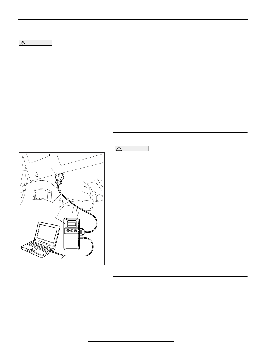
(1) Connect scan tool MB991958. Refer to "How to connect the
."
(2) Turn the ignition switch to the "ON" position.
(3) Diagnose the CAN bus line.
(4) Turn the ignition switch to the "LOCK" (OFF) position.
Q: Is the CAN bus line found to be normal?
YES : Go to Step 2.
NO : Repair the CAN bus line (Refer to GROUP 54C,
).
STEP 2. Recheck for diagnostic trouble code.
Check that the DTC is set in the occupant classification-ECU.
Q: Is the DTC set?
YES : Diagnose the occupant classification-ECU (Refer to
).
NO : Go to Step 3
AC608435
Data link connector
MB991827
MB991824
MB991910
AB