Mitsubishi Evolution X. Manual - part 698


  Index      Mitsubishi     Mitsubishi Evolution X - service repair manual 2008 year


Search            


Content   ..  696  697  698  699   ..


Mitsubishi Evolution X. Manual - part 698


SRS AIR BAG DIAGNOSIS

TSB Revision

SUPPLEMENTAL RESTRAINT SYSTEM (SRS)

52B-239

DTC B1C48: Front Passenger's Pre-tensioner (Squib) System (Shorted to Squib Circuit Power 
Supply)

CAUTION

If DTC B1C48 is set in the SRS-ECU, always diag-
nose the CAN main bus line.

.

CIRCUIT OPERATION

The SRS-ECU judges how severe a collision is by 
detecting signals from the front impact sensors and 
the front air bag analog G-sensor. If the impact is 
over a predetermined level, the SRS-ECU sends an 
ignition signal. At this time, if the front air bag safing 
G-sensor is on, the pre-tensioner will deploy. 

.

DTC SET CONDITIONS

This DTC is set if there is abnormal resistance 
between the input terminals of the passenger's seat 
belt pre-tensioner (squib).

.

TROUBLESHOOTING HITS

• Damaged wiring harnesses or connectors

• Short to the power supply in the passenger's seat 

belt pre-tensioner (squib) harness

• Malfunction of the SRS-ECU
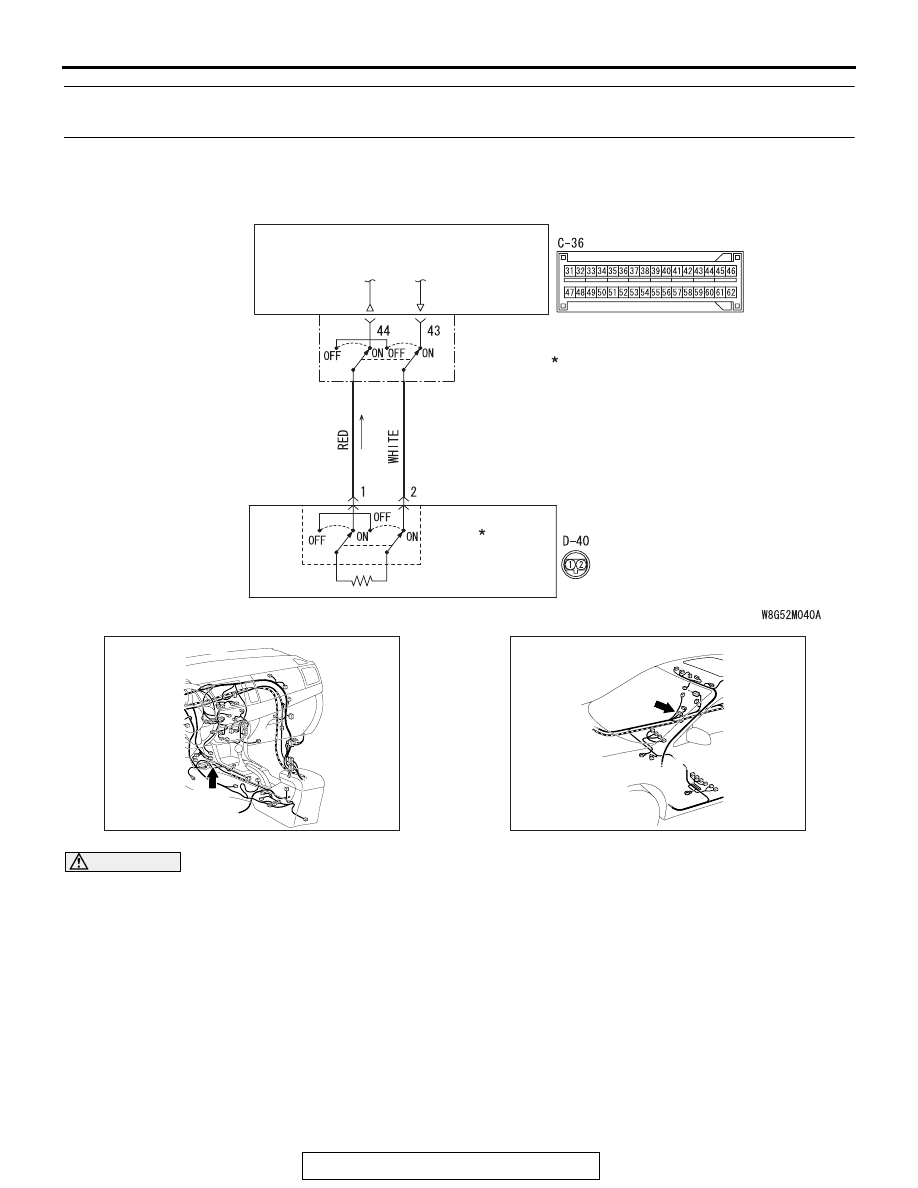
SEAT BELT
PRE-TENSIONER (RH)

CONNECTOR
LOCK 
SWITCH

CONNECTOR
LOCK SWITCH

SRS-ECU

Seat Belt Pre-Tensioner (RH) (Squib) Circuit

AC708951AD

Connector: C-36

C-36 (Y)

AC708954 AH

Connector: D-40

D-40 (B)

SRS AIR BAG DIAGNOSIS

TSB Revision

SUPPLEMENTAL RESTRAINT SYSTEM (SRS)

52B-240

DIAGNOSIS

Required Special Tools:

• MB991958: Scan Tool (M.U.T.-III Sub Assembly)

• MB991824: Vehicle Communication Interface (V.C.I.)

• MB991827: M.U.T.-III USB Cable

• MB991910: M.U.T.-III Main Harness A (Vehicles with 

CAN Communication System)

• MB991865: Dummy resistor

• MB991884: Resister harness

STEP 1. Using scan tool MB991958, diagnose the CAN bus 
line.

CAUTION

To prevent damage to scan tool MB991958, always turn the 
ignition switch to the "LOCK" (OFF) position before con-
necting or disconnecting scan tool MB991958.
(1) Connect scan tool MB991958. Refer to "How to connect the 

scan tool 

P.52B-28

."

(2) Turn the ignition switch to the "ON" position.
(3) Diagnose the CAN bus line.
(4) Turn the ignition switch to the "LOCK" (OFF) position.
Q: Is the CAN bus line found to be normal?

YES : Go to Step 2.
NO :  Repair the CAN bus line (Refer to GROUP 54C, 

Diagnosis 

P.54C-14

).

STEP 2. Recheck for diagnostic trouble code.
Check again if the DTC is set.
(1) Erase the DTC.
(2) Turn the ignition switch to "ON" position.
(3) Check if the DTC is set.
(4) Turn the ignition switch to the "LOCK" (OFF) position.
Q: Is the DTC set?

YES : Go to Step 3.
NO :  There is an intermittent malfunction such as poor 

engaged connector(s) or open circuit (Refer to 
GROUP 00, How to Cope with Intermittent 
Malfunction 

P.00-15

).

AC608435

Data link connector

MB991827

MB991824

MB991910

AB

SRS AIR BAG DIAGNOSIS

TSB Revision

SUPPLEMENTAL RESTRAINT SYSTEM (SRS)

52B-241

STEP 3. Check the passenger's seat belt pre-tensioner.
(1) Disconnect the negative battery terminal.
(2) Disconnect passenger's seat belt pre-tensioner connector 

D-40. Use a flat-tipped screwdriver to unlock the locking 
button at the harness side connector by withdrawing it 
toward you in two stages, and then disconnect the 
connector.

(3) Connect special tool MB991865 to special tool MB991884.
(4) Connect special tool MB991884 to the D-40 harness side 

connector.

(5) Connect the negative battery terminal.
(6) Erase diagnostic trouble code memory, and then check the 

diagnostic trouble code.

Q: Is DTC B1C48 set?

YES : Go to Step 4.
NO :  Replace the passenger's seat belt with pre-tensioner 

(Refer to 

P.52B-413

). Then go to Step 6.

AC609576AB

Pre-tensioner

Harness side
connector

Locking 
button

Flat-tipped
screwdriver

AC301553CC

D-40 Harness side 
connector

MB991884 

(Resistor harness)

MB991865

(Dummy resistor: 3    )

SRS AIR BAG DIAGNOSIS

TSB Revision

SUPPLEMENTAL RESTRAINT SYSTEM (SRS)

52B-242

STEP 4. Check the passenger's seat belt pre-tensioner 
circuit. Measure the voltage at the SRS-ECU connector 
C-36.
(1) Disconnect the negative battery terminal.
(2) While pushing the part "A" indicated in the figure of the 

harness side connector, turn the lock lever to the direction 
of the arrow to release the lock lever, and disconnect the 
C-36 SRS-ECU connector.

DANGER

To prevent the seat belt pre-tensioner from deploying 
unintentionally, disconnect the passenger’s seat belt 
pre-tensioner connector D-40 to short the squib cir-
cuit.

(3) Disconnect passenger's seat belt pre-tensioner connector 

D-40. Use a flat-tipped screwdriver to unlock the locking 
button at the harness side connector by withdrawing it 
toward you in two stages, and then disconnect the 
connector.

CAUTION

Insert an insulator such as a cable tie to a depth of 4mm 
(0.16 inch) or more, otherwise the short spring will not be 
released.
(4) Insert a cable tie [3 mm (0.12 inch) wide, 0.5 mm (0.02 inch) 

thick] between terminals 43, 44 and the short spring to 
release the short spring.

(5) Connect the negative battery terminal.
(6) Ignition switch: "ON".

(7) Measure the voltage between C-36 harness side connector 

terminals 43, 44 and body ground.
Voltage should measure 0 volt.

Q: Is the measured voltage 0 volt?

YES : Erase the diagnostic trouble code memory, and check 

the diagnostic trouble code. If DTC B1C48 sets, 
replace the SRS-ECU (Refer to 

P.52B-383

). Then go 

to Step 6.

NO :  Go to Step 5.

AC507645

A

AC

Lock lever

AC609576AB

Pre-tensioner

Harness side
connector

Locking 
button

Flat-tipped
screwdriver

AC507303 CD

A

A

C-36 Harness side
connector (front view)

Section
A - A

Cable tie

Short spring

4 mm (0.16 inch) or more

Terminal

AC608813

C-36 Harness side 
connector (front view)

BK


Content   ..  696  697  698  699   ..