Mitsubishi Evolution X. Manual - part 661


  Index      Mitsubishi     Mitsubishi Evolution X - service repair manual 2008 year


Search            


Content   ..  659  660  661  662   ..


Mitsubishi Evolution X. Manual - part 661


SRS AIR BAG DIAGNOSIS

TSB Revision

SUPPLEMENTAL RESTRAINT SYSTEM (SRS)

52B-91

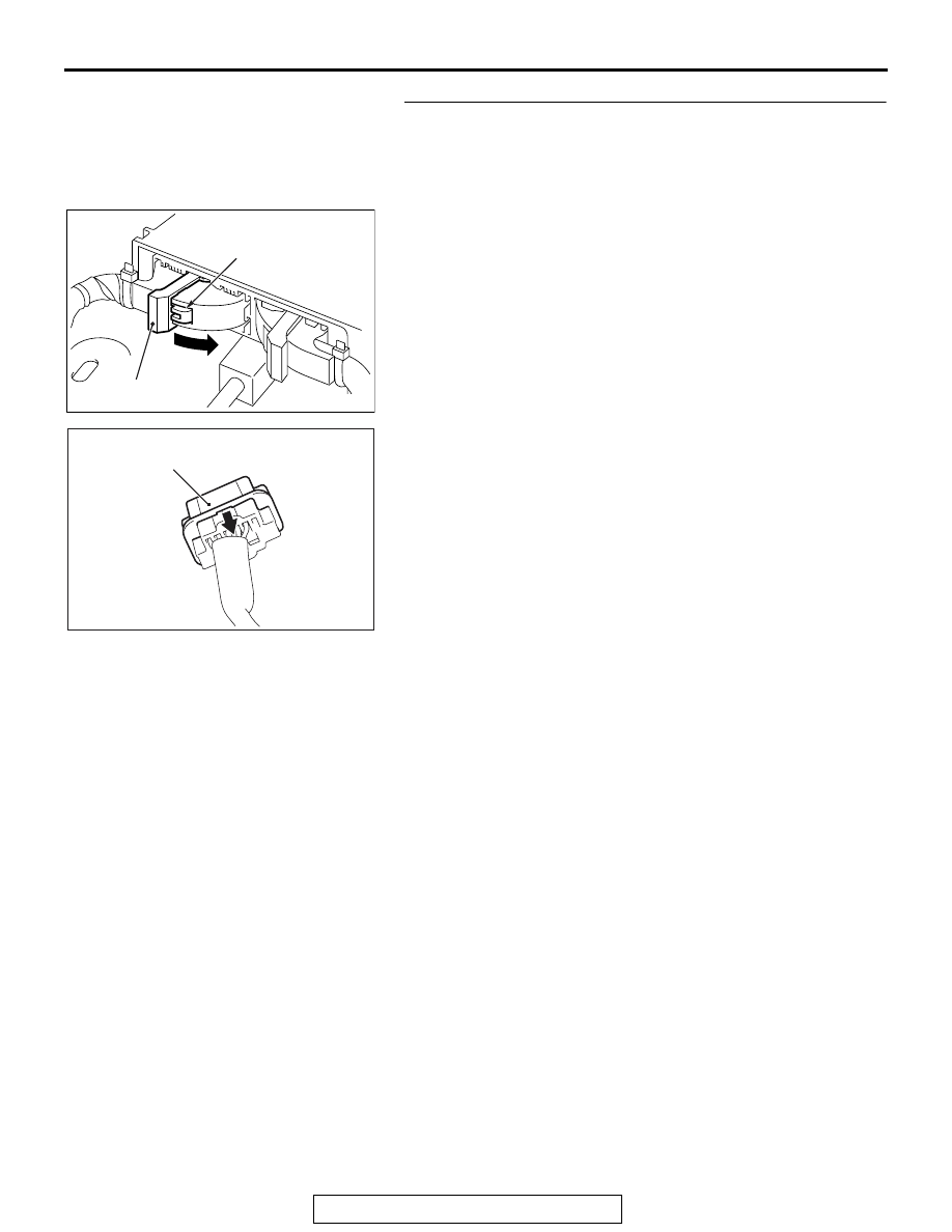
STEP 3. Check SRS-ECU connector C-37 and passenger’s 
(front) air bag module connector C-14.
(1) Disconnect the negative battery terminal.
(2) Disconnect connectors C-37 and C-14 then reconnect 

them.

(3) While pushing the part "A" indicated in the figure of the 

harness side connector, turn the lock lever to the direction 
of the arrow to release the lock lever, and disconnect the 
C-37 SRS-ECU connector.

(4) After disconnecting the connector while sliding the C-14 

harness side connector to the direction of the arrow, 
connect the connector again.

(5) Connect the negative battery terminal.
(6) Erase the diagnostic trouble code memory, and check the 

diagnostic trouble code.

Q: Is DTC B1B0B <1st squib> or B1B0F <2nd squib> set?

YES : Go to Step 4.
NO :  The procedure is complete. It is assumed that DTC 

B1B0B <1st squib> or B1B0F <2nd squib> set as 
connector C-37 or C-14 was engaged improperly.

AC506734

A

AD

Lock lever

AC306561

Passenger's (front) air bag 
module connector C-14

BI

SRS AIR BAG DIAGNOSIS

TSB Revision

SUPPLEMENTAL RESTRAINT SYSTEM (SRS)

52B-92

STEP 4. Check the passenger's (front) air bag module.
(1) Disconnect the negative battery terminal.
(2) Disconnect the passenger’s (front) air bag module 

connector C-14.

(3) Disconnect the connector while sliding the C-14 wiring 

harness side connector to the direction of the arrow.

(4) Connect special tool MB991865 to special tool MB991866.

CAUTION

Do not insert a probe into the terminal from its front side 
directly as the connector contact pressure may be weak-
ened.
(5) Insert special tool MB991866 into the harness side 

connector C-14 (terminal No.1 and 2 <1st squib> or 
terminal No.3 and 4 <2nd squib>) by backprobing.

(6) Connect the negative battery terminal.

CAUTION

Always DTC B1B0E is set when checking DTC B1B0B. This 
is because the second side terminal is isolated when 
checking it. DTC B1B0E is set but this is not a fault. In 
addition, always DTC B1B0A is set when checking DTC 
B1B0F because the first side terminal is isolated. 
(7) Erase the diagnostic trouble code memory, and check the 

diagnostic trouble code.

Q: Is the checked DTC set?

YES : Go to Step 5.
NO :  Replace the passenger's (front) air bag module (Refer 

to 

P.52B-393

). Then go to Step 7

AC306561

Passenger's (front) air bag 
module connector C-14

BI

AC306760AU

MB991865
(Dummy resistor: 3    )

MB991866 
(Resistor harness)

C-14 Harness 

side connector

C-14 Passenger's (front) 

air bag module connector

SRS AIR BAG DIAGNOSIS

TSB Revision

SUPPLEMENTAL RESTRAINT SYSTEM (SRS)

52B-93

STEP 5. Check the passenger’s (front) air bag module 
circuit at SRS-ECU connector C-37.
(1) Disconnect the negative battery terminal.
(2) While pushing the part "A" indicated in the figure of the 

harness side connector, turn the lock lever to the direction 
of the arrow to release the lock lever, and disconnect the 
C-37 SRS-ECU connector.

DANGER

To prevent the air bag from deploying unintentionally, 
disconnect the passenger’s (front) air bag module 
connector C-14 to short the squib circuit.

(3) Disconnect the passenger's (front) air bag module 

connector C-14.

(4) Disconnect the connector while sliding the C-14 wiring 

harness side connector to the direction of the arrow.

CAUTION

Insert an insulator such as a cable tie to a depth of 4 mm 
(0.16 inch) or more, otherwise the short spring will not be 
released.
(5) Insert a cable tie [3 mm (0.12 inch) wide, 0.5 mm (0.02 inch) 

thick] between terminals 7 and 8 <1st squib> or 11 and 12 
<2nd squib>, and the short spring to release the short 
spring.

AC506734

A

AD

Lock lever

AC306561

Passenger's (front) air bag 
module connector C-14

BI

AC507302 BH

A

A

<1st Squib>

C-37 Harness side
connector (front view)

Section
A - A

Cable tie

Short spring

4 mm (0.16 inch) or more

Terminal

AC507302 BI

A

A

<2nd Squib>

C-37 Harness side
connector (front view)

Section
A - A

Cable tie

Short spring

4 mm (0.16 inch) or more

Terminal

SRS AIR BAG DIAGNOSIS

TSB Revision

SUPPLEMENTAL RESTRAINT SYSTEM (SRS)

52B-94

(6) Check for continuity between C-37 harness side connector 

terminals 7 and 8 <1st squib> or 11 and 12 <2nd squib>.
It should be open circuit.

Q: Is it open circuit?

YES : Erase the diagnostic trouble code memory, and check 

the diagnostic trouble code. If DTC B1B0B <1st 
squib> or B1B0F <2nd squib> set, replace the 
SRS-ECU (Refer to 

P.52B-383

). Then go to Step 7.

NO :  Go to Step 6. 

STEP 6. Check the harness for short circuit between 
SRS-ECU connector C-37 (terminal No.7 and 8 <1st squib> 
or terminal No.11 and 12 <2nd squib>) and passenger's 
(front) air bag module connector C-14 (terminal No.2 and 1 
<1st squib> terminal No.4 and 3 <2nd squib>).
Q: Are harness wires between SRS-ECU connector C-37 

(terminal No.7 and 8 <1st squib> or terminal No.11 and 
12 <2nd squib>) and passenger's (front) air bag module 
connector C-14 (terminal No.2 and 1 <1st squib> 
terminal No.4 and 3 <2nd squib>) in good condition?
YES : 
Go to Step 7.
NO :  Replace the harness wires between SRS-ECU 

connector C-37 and passenger’s (front) air bag 
module connector C-14. Then go to Step 7.

STEP 7. Check for diagnostic trouble code.
Check again if the DTC is set.
(1) Erase the DTC.
(2) Turn the ignition switch to the "ON" position.
(3) Check if the DTC is set.
(4) Turn the ignition switch to the "LOCK" (OFF) position.
Q: Is DTC B1B0B <1st squib> or B1B0F <2nd squib> set?

YES : Return to Step 1.
NO :  The procedure is complete.

AC608812

C-37 Harness side 
connector (front view)

FC

<1st squib>

AC608812

C-37 Harness side 
connector (front view)

FD

<2nd squib>


Content   ..  659  660  661  662   ..