Mitsubishi Evolution X. Manual - part 654
SRS AIR BAG DIAGNOSIS
TSB Revision
SUPPLEMENTAL RESTRAINT SYSTEM (SRS)
52B-63
DTC B1B03: Driver's Air Bag Module (1st squib) System (Short Circuit Between Squib Circuit
Terminals)
DTC B1B07: Driver's Air Bag Module (2nd squib) System (Short Circuit Between Squib Circuit
Terminals)
CAUTION
If DTC B1B03 <1st squib> or B1B07 <2nd squib>
is set in the SRS-ECU, always diagnose the CAN
bus lines.
.
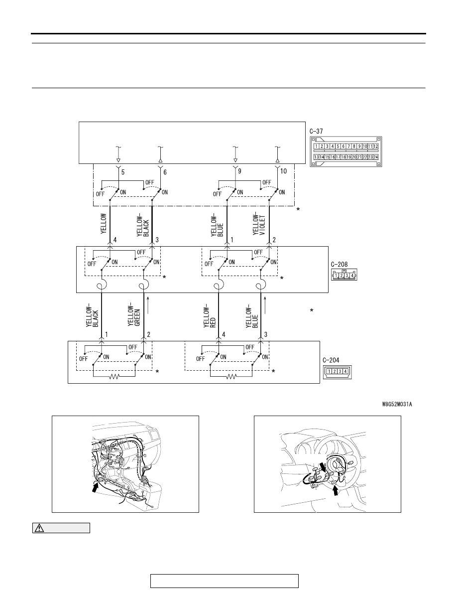
SRS-ECU
CLOCK
SPRING
DRIVER'S AIR BAG
MODULE (SQUIB)
CONNECTOR LOCK SWITCH
CONNECTOR COUPLED: ON
CONNECTOR UNCOUPLED: OFF
NOTE
:
Driver's Air Bag Module (Squib) Circuit
AC708951AC
C-37 (Y)
Connector: C-37
AC708953AB
Connectors: C-204, C-208
C-208 (Y)
C-204 (Y)