Mitsubishi Evolution X. Manual - part 617
DIAGNOSIS
TSB Revision
WIRELESS CONTROL MODULE (WCM)
42C-85
SYMPTOM PROCEDURES
Inspection Procedure 1: Scan tool cannot communicate with WCM.
CAUTION
Before replacing the ECU, ensure that the com-
munication circuit is normal.
.
TECHNICAL DESCRIPTION (COMMENT)
If the M.U.T.-III cannot communicate with the WCM,
the CAN bus lines may be defective. If the WCM
does not work, the WCM or the power supply circuit
may be defective.
.
TROUBLESHOOTING HINTS
• Malfunction of the power supply or ground of
WCM
• Malfunction of CAN bus line
• Malfunction of WCM
DIAGNOSIS
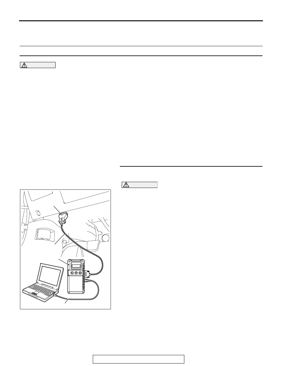
Required Special Tools:
• MB991958 Scan Tool (M.U.T.-III Sub Assembly)
• MB991824: Vehicle Communication Interface (V.C.I.)
• MB991827 M.U.T.-III USB Cable
• MB991910 M.U.T.-III Main Harness A
STEP 1. Using scan tool MB991958, diagnose the CAN bus
line.
CAUTION
To prevent damage to scan tool MB991958, always turn the
ignition switch to the "LOCK" (OFF) position before con-
necting or disconnecting scan tool MB991958.
(1) Connect scan tool MB991958. Refer to "How to connect the
Scan Tool (M.U.T.-III)
(2) Turn the ignition switch to the "ON" position.
(3) Diagnose the CAN bus line.
(4) Turn the ignition switch to the "LOCK" (OFF) position.
Q: Is the CAN bus line found to be normal?
YES : Go to Step 2.
NO : Repair the CAN bus line (Refer to GROUP 54C,
).
AC608435
Data link connector
MB991827
MB991824
MB991910
AB