Mitsubishi Evolution X. Manual - part 613
DIAGNOSIS
TSB Revision
WIRELESS CONTROL MODULE (WCM)
42C-69
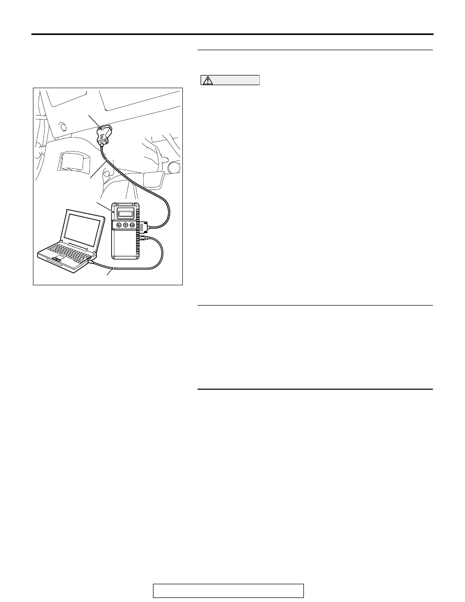
STEP 1. Using scan tool MB991958, diagnose the CAN bus
line.
CAUTION
To prevent damage to scan tool MB991958, always turn the
ignition switch to the "LOCK" (OFF) position before con-
necting or disconnecting scan tool MB991958.
(1) Connect scan tool MB991958. Refer to "How to connect the
Scan Tool (M.U.T.-III)
(2) Turn the ignition switch to the "ON" position.
(3) Diagnose the CAN bus line.
(4) Turn the ignition switch to the "LOCK" (OFF) position.
Q: Is the CAN bus line found to be normal?
YES : Go to Step 2.
NO : Repair the CAN bus line (Refer to GROUP 54C,
).
STEP 2. Using scan tool MB991958, read the combination
meter diagnostic trouble code.
Check if DTC is set to the combination meter.
Q: Is the DTC set?
YES : Troubleshoot the combination meter (Refer to
GROUP 54A, Diagnosis
NO : Go to Step 3.
STEP 3. Recheck for diagnostic trouble code.
Check again if the DTC is set to the WCM.
(1) Erase the DTC.
(2) Turn the ignition switch from "LOCK" (OFF) position to "ON"
position.
(3) Check if DTC is set.
(4) Turn the ignition switch to the "LOCK" (OFF) position.
Q: Is the DTC set?
YES : Replace WCM and register the ID codes (Refer to
NO : The trouble can be an intermittent malfunction such
as a poor connection or open circuit in the CAN bus
lines between the combination meter and the WCM.
(Refer to GROUP 00, How to Cope with Intermittent
Malfunction
).
AC608435
Data link connector
MB991827
MB991824
MB991910
AB