Mitsubishi Evolution X. Manual - part 609
DIAGNOSIS
TSB Revision
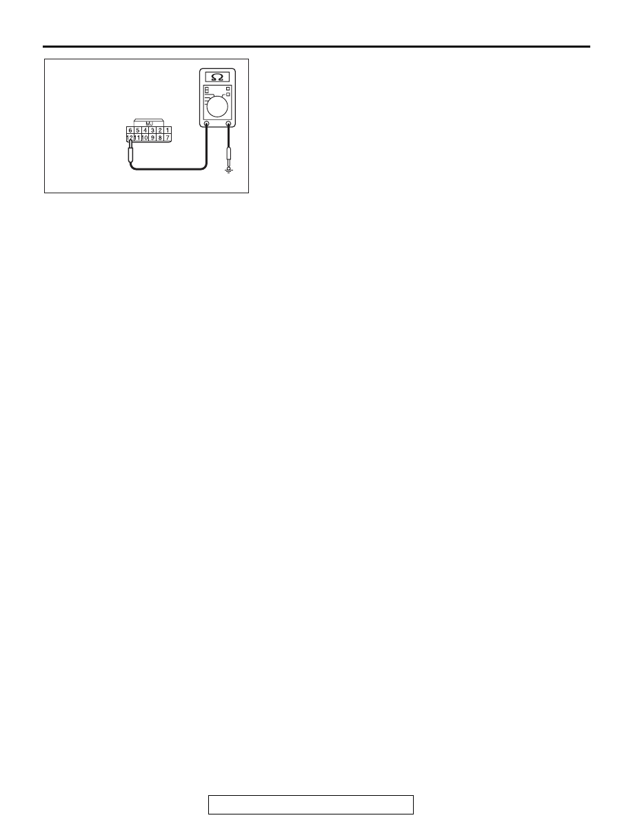
WIRELESS CONTROL MODULE (WCM)
42C-53
•
Terminal No.12
− body ground.
OK: No continuity
Q: Is the check result normal?
YES : Go to Step 5.
NO (terminal No.1
− body ground.) : The wiring harness
between D-14 receiver antenna assembly connector
terminal No.1 and C-07 WCM connector terminal
No.1 is shorted to ground. Repair the wiring
harness.and then register the ID codes. (Refer to
.) Then go to Step 8.
NO (terminal No.3
− body ground.) : The wiring harness
between D-14 receiver antenna assembly connector
terminal No.3 and C-07 WCM connector terminal
No.3 is shorted to ground. Repair the wiring
harness.and then register the ID codes. (Refer to
.) Then go to Step 8.
NO (terminal No.5
− body ground.) : The wiring harness
between D-14 receiver antenna assembly connector
terminal No.5 and C-07 WCM connector terminal
No.5 is shorted to ground. Repair the wiring
harness.and then register the ID codes. (Refer to
.) Then go to Step 8.
NO (terminal No.8
− body ground.) : The wiring harness
between D-14 receiver antenna assembly connector
terminal No.8 and C-07 WCM connector terminal
No.8 is shorted to ground. Repair the wiring
harness.and then register the ID codes. (Refer to
.) Then go to Step 8.
NO (terminal No.12
− body ground.) : The wiring harness
between D-14 receiver antenna assembly connector
terminal No.12 and C-07 WCM connector terminal
No.12 is shorted to ground. Repair the wiring
harness.and then register the ID codes. (Refer to
.) Then go to Step 8.
AC709322 CC
Harness side: D-14