Mitsubishi Evolution X. Manual - part 605


  Index      Mitsubishi     Mitsubishi Evolution X - service repair manual 2008 year


Search            


Content   ..  603  604  605  606   ..


Mitsubishi Evolution X. Manual - part 605


DIAGNOSIS

TSB Revision

WIRELESS CONTROL MODULE (WCM)

42C-37

DTC B2352: Antenna fail

.

DTC SET CONDITION

WCM sets DTC B2352 when open or short circuit to 
the ground in the antenna is detected.

.

TECHNICAL DESCRIPTION (COMMENT)

When the ignition switch is turned ON, WCM trans-
mits signal to the antenna. When the antenna is 
found faulty, WCM determines that the abnormality is 
present.

.

TROUBLESHOOTING HINT

Malfunction of WCM (Open circuit in antenna)

DIAGNOSIS

Required Special Tools:

• MB991958: Scan Tool (M.U.T.-III Sub Assembly)

• MB991824: Vehicle Communication Interface (V.C.I.)

• MB991827: M.U.T.-III USB Cable

• MB991910: M.U.T.-III Main Harness A

Recheck for diagnostic trouble code.
Check again if the DTC is set to the WCM.
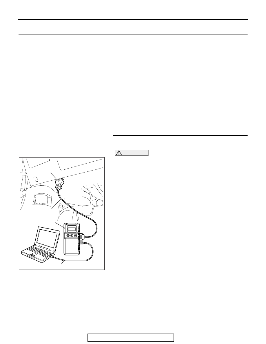
CAUTION

To prevent damage to scan tool (MB991958), always turn 
the ignition switch to the "LOCK" (OFF) position before 
connecting or disconnecting scan tool (MB991958).
(1) Connect scan tool MB991958 to the data link connector.

Erase the DTC.

(2) Turn the ignition switch from "LOCK" (OFF) position to "ON" 

position.

(3) Check if DTC is set.
(4) Turn the ignition switch to the "LOCK" (OFF) position.
Q: Is the DTC set?

YES : Replace WCM and register the ID codes (Refer to 

P.42C-9

).

NO :  The procedure is complete.

AC608435

Data link connector

MB991827

MB991824

MB991910

AB

DIAGNOSIS

TSB Revision

WIRELESS CONTROL MODULE (WCM)

42C-38

DTC B2401: Keyless/KOS key ID not register

CAUTION

• If DTC B2401 is set, be sure to diagnose the 

CAN bus line.

• When replacing the ECU, always check that 

the communication circuit is normal.

.

DTC SET CONDITION

If the keyless ID registered transmitter is not regis-
tered to the WCM, the WCM sets the DTC No. 
B2401.

.

TECHNICAL DESCRIPTION (COMMENT)

If the number of keyless ID registered transmitter is 
zero, the WCM determines that there is a problem.

.

TROUBLESHOOTING HINTS

• Malfunction of CAN bus line

• Failure of transmitter registration process

• Malfunction of WCM

DIAGNOSIS

Required Special Tools:

• MB991958: Scan Tool (M.U.T.-III Sub Assembly)

• MB991824: Vehicle Communication Interface (V.C.I.)

• MB991827: M.U.T.-III USB Cable

• MB991910: M.U.T.-III Main Harness A

STEP 1. Using scan tool MB991958, diagnose the CAN bus 
line.

CAUTION

To prevent damage to scan tool (MB991958), always turn 
the ignition switch to the "LOCK" (OFF) position before 
connecting or disconnecting scan tool (MB991958).
(1) Connect scan tool MB991958 to the data link connector.
(2) Turn the ignition switch to the "ON" position.
(3) Diagnose the CAN bus line.
(4) Turn the ignition switch to the "LOCK" (OFF) position.
Q: Is the CAN bus line found to be normal?

YES : Go to Step 2.
NO :  Repair the CAN bus line (Refer to GROUP 54C, 

Diagnosis 

P.54C-14

).

AC608435

Data link connector

MB991827

MB991824

MB991910

AB

DIAGNOSIS

TSB Revision

WIRELESS CONTROL MODULE (WCM)

42C-39

STEP 2. Register the keyless ID and recheck the 
diagnostic trouble code.
Register the keyless ID (Refer to 

P.42C-9

), and recheck if the 

DTC is set.
(1) Erase the DTC.
(2) Turn the ignition switch from the "LOCK" (OFF) position to 

the "ON" position.

(3) Check if the DTC is set.
Q: Is the DTC set?

YES : Replace WCM and register the ID codes (Refer to 

P.42C-9

).

NO :  The procedure is complete.

DTC B2415: RA module power voltage

CAUTION

• If DTC B2415 is set, diagnose the CAN bus 

lines.

• When replacing the ECU, always check that 

the communication circuit is normal.

AC709290

JOINT 
CONNECTOR (6)

RECEIVER

KEYLESS 
ENTRY 
TRANSMITTER

WIRELESS 
CONTROL 
MODULE

RECEIVER 
ANTENNA 
ASSEMBLY

Wireless Control Module System Input Signal

AB

RED

RED

GREEN -RED

GREEN -RED

YELLOW

-GREEN

YELLOW

-GRAY

YELLOW

-GRAY

BROWN -WHITE

BROWN -WHITE

RED- WHITE

RED- WHITE

RED

GREEN -RED

BROWN -WHITE

RED- WHITE

DIAGNOSIS

TSB Revision

WIRELESS CONTROL MODULE (WCM)

42C-40

.

DTC SET CONDITION

If an open circuit or short to ground occurs in the 
receiver antenna assembly, WCM sets DTC B2415.

.

TECHNICAL DESCRIPTION (COMMENT)

The receiver antenna assembly receives the trans-
mitter signal. The receiver antenna assembly trans-
mits the received signal to the WCM. If an open 
circuit or short to ground occurs on the wiring har-
ness between WCM and receiver antenna assembly 
at this time, WCM determines that there is a prob-
lem.

.

TROUBLESHOOTING HINTS

• Malfunction of CAN bus line

• Malfunction of the receiver antenna assembly

• Malfunction of the WCM

• Damaged wiring harness and connectors

DIAGNOSIS

Required Special Tools:

• MB991958 Scan Tool (M.U.T.-III Sub Assembly)

• MB991824: Vehicles Communication Interface (V.C.I.)

• MB991827 M.U.T.-III USB Cable

• MB991910 M.U.T.-III Main Harness A

AC708951AY

Connectors: C-07, C-16

C-16 (B)

C-07

AC708950BA

Connector: C-41

AC708955AM

Connector: D-14


Content   ..  603  604  605  606   ..