Mitsubishi Evolution X. Manual - part 554


  Index      Mitsubishi     Mitsubishi Evolution X - service repair manual 2008 year


Search            


Content   ..  552  553  554  555   ..


Mitsubishi Evolution X. Manual - part 554


DIAGNOSIS

TSB Revision

KEYLESS OPERATION SYSTEM (KOS)

42B-123

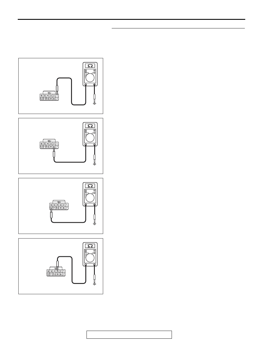
STEP 4. Check the wiring harness between the receiver 
antenna assembly connector D-14 (terminal Nos.1, 8, 12, 3, 
5) and the ground for short circuit.
(1) Disconnect reciever anntena assembly connector D-14, 

and check the wiring harness.

(2) Check the wiring harness between reciever anntena 

assembly connector D-14 (terminal No.1) and ground

OK: No continuity

(3) Check the wiring harness between reciever anntena 

assembly connector D-14 (terminal No.8) and and ground

OK: No continuity

(4) Check the wiring harness between reciever anntena 

assembly connector D-14 (terminal No.12) and and ground

OK: No continuity

(5) Check the wiring harness between reciever anntena 

assembly connector D-14 (terminal No.3) and ground

OK: No continuity

AC709707FZ

Harness side: D-14

AC709707FY

Harness side: D-14

AC709707FX

Harness side: D-14

AC709707FW

Harness side: D-14

DIAGNOSIS

TSB Revision

KEYLESS OPERATION SYSTEM (KOS)

42B-124

(6) Check the wiring harness between reciever anntena 

assembly connector D-14 (terminal No.5) and ground

OK: No continuity

Q: Is the wiring harness between receiver antenna 

assembly connector D-14 (terminal Nos.1, 8, 12, 3, 5) 
and the ground in good condition?
YES  : 
Go to Step 5.
NO (receiver antenna assembly connector D-14 terminal 
No.1  

 ground.) : Repair the wiring harness between 

receiver antenna assembly connector D-14  (terminal 
No.1) and the KOS-ECU connector C-05 (terminal 
No.12).

NO (receiver antenna assembly connector D-14 terminal 
No.8 

 ground.) : Repair the wiring harness between 

receiver antenna assembly connector D-14  (terminal 
No.8) and the ground.

NO (receiver antenna assembly connector D-14 terminal 
No.12 

 ground.) : Repair the wiring harness between 

receiver antenna assembly connector D-14  (terminal 
No.12) and the ground.

NO (receiver antenna assembly connector D-14 terminal 
No.3 

 ground.) : Repair the wiring harness between 

receiver antenna assembly connector D-14  (terminal 
No.3) and the ground.

NO (receiver antenna assembly connector D-14 terminal 
No.5 

 ground.) : Repair the wiring harness between 

receiver antenna assembly connector D-14  (terminal 
No.5) and the ground.

STEP 5. Replace the receiver antenna assembly, and check 
whether the diagnostic trouble code is reset.
(1) Turn the ignition switch from the "LOCK" (OFF) position to 

the "ON" position.

(2) Check if the DTC is set.
Q: Is the DTC set?

YES : Go to Step 6.
NO :  The procedure is complete.

AC709707FV

Harness side: D-14

DIAGNOSIS

TSB Revision

KEYLESS OPERATION SYSTEM (KOS)

42B-125

STEP 6. Check the wiring harness between the receiver 
antenna module connector C-08 (terminal Nos. 2, 1, 8, 12) 
and the KOS-ECU connector C-05 (terminal Nos. 11, 12, 32, 
7) for open circuit.
(1) Disconnect reciever anntena module connector C-08 and 

KOS-ECU connector C-05, and check the wiring harness.

(2) Check the wiring harness between reciever anntena 

module connector C-08 (terminal No.2) and KOS-ECU 
connector C-05 (terminal No.11)

OK: Continuity exists (2 

 or less)

(3) Check the wiring harness between reciever anntena 

module connector C-08 (terminal No.1) and KOS-ECU 
connector C-05 (terminal No.12)

OK: Continuity exists (2 

 or less)

(4) Check the wiring harness between reciever anntena 

module connector C-08 (terminal No.8) and KOS-ECU 
connector C-05 (terminal No.32)

OK: Continuity exists (2 

 or less)

AC709707

Harness side: C-05

DZ

Harness side: C-08

AC709707

Harness side: C-05

DZ

Harness side: C-08

AC709707

Harness side: C-05

EB

Harness side: C-08

DIAGNOSIS

TSB Revision

KEYLESS OPERATION SYSTEM (KOS)

42B-126

(5) Check the wiring harness between reciever anntena 

module connector C-08 (terminal No.12) and KOS-ECU 
connector C-05 (terminal No.7)

OK: Continuity exists (2 

 or less)

Q: Is the wiring harness between receiver antenna module 

connector C-08 (terminal Nos. 2, 1, 8, 12) and the 
KOS-ECU connector C-05 (terminal Nos. 11, 12, 32, 7) in 
good condition?
YES  : 
Go to Step 7.
NO (receiver antenna module connector C-08 terminal 
No.2 

 KOS-ECU connector C-05 terminal No.11.) : 

Repair the wiring harness between receiver antenna 
module connector C-08  (terminal No. 2) and the 
KOS-ECU connector C-05 (terminal No. 11).

NO (receiver antenna module connector C-08 terminal 
No.1 

 KOS-ECU connector C-05 terminal No.12.) : 

Repair the wiring harness between receiver antenna 
module connector C-08  (terminal No. 1) and the 
KOS-ECU connector C-05 (terminal No. 12).

NO (receiver antenna module connector C-08 terminal 
No.8 

 KOS-ECU connector C-05 terminal No.32.) : 

Repair the wiring harness between receiver antenna 
module connector C-08  (terminal No. 8) and the 
KOS-ECU connector C-05 (terminal No. 32).

NO (receiver antenna module connector C-08 terminal 
No.12 

 KOS-ECU connector C-05 terminal No.7.) : 

Repair the wiring harness between receiver antenna 
module connector C-08  (terminal No. 12) and the 
KOS-ECU connector C-05 (terminal No. 7).

AC709707EC

Harness side: C-08

Harness side: C-05


Content   ..  552  553  554  555   ..