Mitsubishi Evolution X. Manual - part 551


  Index      Mitsubishi     Mitsubishi Evolution X - service repair manual 2008 year


Search            


Content   ..  549  550  551  552   ..


Mitsubishi Evolution X. Manual - part 551


DIAGNOSIS

TSB Revision

KEYLESS OPERATION SYSTEM (KOS)

42B-111

STEP 6. Replace the key reminder switch, and check 
whether the diagnostic trouble code is reset.
(1) Erase the DTC.
(2) Turn the ignition switch from the "LOCK" (OFF) position to 

the "ON" position.

(3) Check if the DTC is set.
Q: Is the DTC set?

YES : Replace KOS-ECU and register the ID codes (Refer 

to 

P.42B-12

).

NO :  The procedure is complete.

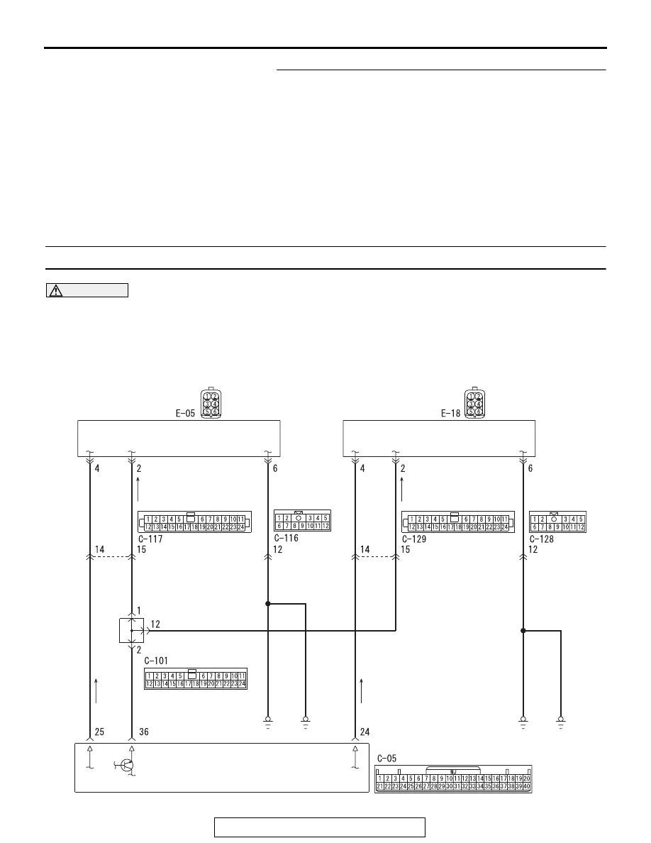
DTC B2414: Unlock sensor fail

CAUTION

• If DTC No. B2414 is set, diagnose the CAN 

bus lines.

• When replacing the ECU, always check that 

the communication circuit is normal.

AC709349

KOS-ECU

UNLOCK SENSOR 
(FRONT DOOR: RH)

UNLOCK SENSOR
(FRONT DOOR: LH)

JOINT
CONNECTOR (1)

YELLO

W

-PINK

WHITE

WHITE

WHITE

BLA

CK

BLA

CK

BLA

CK

BLA

CK

BLA

CK

BLA

CK

BLA

CK

BLA

CK

LIGHT  GREEN

LIGHT  GREEN

LIGHT  GREEN

LIGHT  GREEN

LIGHT  GREEN

Unlock Sensor Circuit

AB

DIAGNOSIS

TSB Revision

KEYLESS OPERATION SYSTEM (KOS)

42B-112

.

DTC SET CONDITION

If KOS-ECU detects an abnormality in power supply 
of the unlock sensor, KOS-ECU sets DTC No. 
B2414.

.

TECHNICAL DESCRIPTION (COMMENT)

If an abnormality in power supply of the unlock sen-
sor is detected when power supply of it is turned on, 
KOS-ECU determines that there is a problem. 

.

TROUBLESHOOTING HINTS

• Damaged wiring harness and connectors

• Malfunctions of the unlock sensor

• Malfunction of the KOS-ECU

DIAGNOSIS

Required Special Tools:

• MB992006: Extra fine probe

• MB991223: Harness set

• MB991958: Scan Tool (M.U.T.-III Sub Assembly)

• MB991824: Vehicles Communication Interface (V.C.I.)

• MB991827: M.U.T.-III USB Cable

• MB991910: M.U.T.-III Main Harness A

AC708950BI

C-129 (BR)

C-101 (B)

C-05

Connectors: C-05, C-101, C-129

AC708951BB

C-117 (BR)

Connector: C-117

AC608168 AD

Connector: E-05

AC608167AP

Connector: E-18

DIAGNOSIS

TSB Revision

KEYLESS OPERATION SYSTEM (KOS)

42B-113

STEP 1. Using scan tool MB991958, read CAN bus the 
diagnostic trouble code.

CAUTION

To prevent damage to scan tool MB991958, always turn the 
ignition switch to the "LOCK" (OFF) position before con-
necting or disconnecting scan tool MB991958.
(1) Connect scan tool MB991958. Refer to "How to connect 

scan tool (M.U.T.-III) 

P.42B-10

."

(2) Turn the ignition switch to the "ON" position.
(3) Check whether the CAN bus lines related DTC is set.
(4) Turn the ignition switch to the "LOCK" (OFF) position.
Q: Is the DTC set?

YES : Repair the CAN bus line (Refer to GROUP 54C, CAN 

bus diagnostics table 

P.54C-14

).

NO :  Go to Step 2.

STEP 2. Check KOS-ECU connector C-05, unlock sensor 
(front door: LH) connector E-18 and unlock sensor (front 
door: RH) connector E-05 for loose, corroded or damaged 
terminals, or terminals pushed back in the connector.
Q: Are KOS-ECU connector C-05, unlock sensor (front 

door: LH) connector E-18 and unlock sensor (front 
door: RH) connector E-05 in good condition?
YES : 
Go to Step 3.
NO :  Repair or replace the damaged component(s). Refer 

to GROUP 00E, Harness Connector Inspection 

P.00E-2

. Check that the unlock sensor works 

normally.

AC608435

Data link connector

MB991827

MB991824

MB991910

AB

DIAGNOSIS

TSB Revision

KEYLESS OPERATION SYSTEM (KOS)

42B-114

STEP 3. Check the wiring harness between the KOS-ECU 
connector C-05 (terminal Nos. 24, 36) and unlock sensor 
(front door: LH) connector E-18 (terminal Nos. 4, 2) for 
open circuit.
(1) Disconnect KOS-ECU connector C-05 and unlock sensor 

(front door: LH) connector E-18, and check the wiring 
harness.

(2) Check the wiring harness between KOS-ECU connector 

C-05 (terminal No.24) and unlock sensor (front door: LH) 
connector E-18 (terminal No.4).

OK: Continuity exists (2 

 or less)

(3) Check the wiring harness between KOS-ECU connector 

C-05 (terminal No.36) and unlock sensor (front door: LH) 
connector E-18 (terminal No.2).

OK: Continuity exists (2 

 or less)

Q: Is the wiring harness between KOS-ECU connector C-05 

(terminal Nos. 24, 36) and unlock sensor (front door: 
LH) connector E-18 (terminal Nos. 4, 2) in good 
condition?
YES  : 
Go to Step 4.
NO (KOS-ECU connector C-05 terminal No.24 

 unlock 

sensor (front door: LH) connector E-18 terminal No.4.) : 

Repair the wiring harness between KOS-ECU 
connector C-05 (terminal No.24) and unlock sensor 
(front door: LH) connector E-18 (terminal No.4).

NO (KOS-ECU connector C-05 terminal No.36 

 unlock 

sensor (front door: LH) connector E-18 terminal No.2.) : 

Repair the wiring harness between KOS-ECU 
connector C-05 (terminal No.36) and unlock sensor 
(front door: LH) connector E-18 (terminal No.2).

AC709707

Harness side: C-05

GK

Harness side: E-18

AC709707GL

Harness side: C-05

Harness side: E-18


Content   ..  549  550  551  552   ..