Mitsubishi Evolution X. Manual - part 548


  Index      Mitsubishi     Mitsubishi Evolution X - service repair manual 2008 year


Search            


Content   ..  546  547  548  549   ..


Mitsubishi Evolution X. Manual - part 548


DIAGNOSIS

TSB Revision

KEYLESS OPERATION SYSTEM (KOS)

42B-99

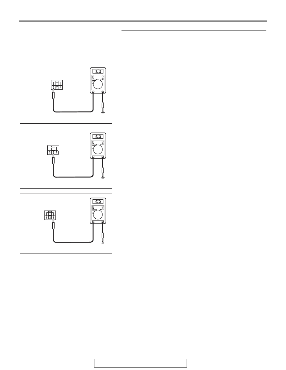
STEP 3. Check the wiring harness between the inside 
transmitter antenna assembly (rear) connector F-02 
(terminal Nos. 3, 2, 1) and the ground for short circuit.
(1) Disconnect inside transmitter antenna assembly (rear) 

connector F-02, and check the wiring harness.

(2) Check the wiring harness between inside transmitter 

antenna assembly (rear) connector F-02 (terminal No.3) 
and ground

OK: No continuity

(3) Check the wiring harness between inside transmitter 

antenna assembly (rear) connector F-02 (terminal No.2) 
and ground

OK: No continuity

(4) Check the wiring harness between inside transmitter 

antenna assembly (rear) connector F-02 (terminal No.1) 
and ground

OK: No continuity

Q: Is the wiring harness between inside transmitter 

antenna assembly (rear) connector F-02 (terminal Nos. 
3, 2, 1) and the ground in good condition?
YES  : 
Go to Step 4.
NO [inside transmitter antenna assembly (rear) 
connector F-02 terminal No.3 

 ground.] : Repair the 

wiring harness between inside transmitter antenna 
assembly (rear) connector F-02 (terminal No.3) and 
ground.

NO [inside transmitter antenna assembly (rear) 
connector F-02 terminal No.2 

 ground.] : Repair the 

wiring harness between inside transmitter antenna 
assembly (rear) connector F-02 (terminal No.2) and 
the ground.

NO [inside transmitter antenna assembly (rear) 
connector F-02 terminal No.1 

 ground.] : Repair the 

wiring harness between inside transmitter antenna 
assembly (rear) connector F-02 (terminal No.1) and 
the ground.

AC709707IO

Harness side: F-02

AC709707IP

Harness side: F-02

AC709707IQ

Harness side: F-02

DIAGNOSIS

TSB Revision

KEYLESS OPERATION SYSTEM (KOS)

42B-100

STEP 4. Keyless operation system communication test
Check that the communication with the inside transmitter 
antenna assembly (rear) is normal (Refer to Antenna Test 

P.42B-275

).

Antennas to be checked

• rear antenna (interior)

OK: Normal is displayed.

Q: Is the check result normal?

YES : Go to Step 5.
NO :  Replace the inside transmitter antenna assembly 

(rear).

STEP 5. Check whether the diagnostic trouble code is 
reset.
(1) Erase the DTC.
(2) Turn the ignition switch from the LOCK (OFF) position to the 

ON position.

(3) Check if the DTC is set.
Q: Is the DTC set?

YES : Replace KOS-ECU and register the ID codes (Refer 

to 

P.42B-12

).

NO :  The procedure is complete.

DIAGNOSIS

TSB Revision

KEYLESS OPERATION SYSTEM (KOS)

42B-101

DTC B2412: LF antenna power voltage

CAUTION

• If DTC No. B2412 is set, diagnose the CAN 

bus lines.

• When replacing the ECU, always check that 

the communication circuit is normal.

AC609427

KOS-ECU

KEYLESS 

OPERATION 

KEY

OUTSIDE TRANSMISSION 

ANTENNA ASSEMBLY 

(TRUNK LID)

INSIDE TRANSMISSION 

ANTENNA ASSEMBLY 

(REAR)

OUTSIDE TRANSMISSION 

ANTENNA ASSEMBLY 

(DRIVER'S SIDE)

INSIDE TRANSMISSION 

ANTENNA ASSEMBLY 

(FRONT)

OUTSIDE TRANSMISSION 

ANTENNA ASSEMBLY 

(PASSENGER'S SIDE)

SKY  BLUE

RED- BLA

CK

RED- YELLO

W

RED- YELLO

W

SKY  BLUE

SKY  BLUE

SKY  BLUE

BLUE

BLUE

SKY  BLUE

RED- BLA

CK

RED- BLA

CK

RED- BLA

CK

RED- BLA

CK

YELLO

W

YELLO

W

SKY  BLUE

SKY  BLUE

SKY  BLUE

SKY  BLUE

RED- BLA

CK

RED- BLA

CK

RED- BLA

CK

RED- BLA

CK

BLA

CK

-BLUE

BLA

CK

-WHITE

BLA

CK

-BLUE

ORANGE

ORANGE

ORANGE

 Transmission Antenna assembly Circuit

AC

DIAGNOSIS

TSB Revision

KEYLESS OPERATION SYSTEM (KOS)

42B-102

.

DTC SET CONDITION

If KOS-ECU detects an abnormality in power supply 
of the outside or inside antennas, KOS-ECU sets the 
DTC No. B2412.

.

TECHNICAL DESCRIPTION (COMMENT)

If an abnormality in power supply of the outside or 
inside transmitter antenna is detected when power 
supply of it is turned on, KOS-ECU determines that 
there is a problem.

.

TROUBLESHOOTING HINTS

• Damaged wiring harness and connectors

• Malfunction of the KOS-ECU

DIAGNOSIS

Required Special Tools:

• MB992006: Extra fine probe

• MB991223: Harness set

• MB991958: Scan Tool (M.U.T.-III Sub Assembly)

• MB991824: Vehicles Communication Interface (V.C.I.)

• MB991827: M.U.T.-III USB Cable

• MB991910: M.U.T.-III Main Harness A

AC708950AZ

Connector: C-05

AC708951BA

C-121

C-23

Connectors: C-23, C-121

AC708955AS

D-17 (BR)

D-11

D-23

Connectors: D-11, D-17, D-23

AC708954 AP

Connector: D-42

AC708970AM

Connectors: F-02, F-20

F-20

F-20 (GR)


Content   ..  546  547  548  549   ..