Mitsubishi Evolution X. Manual - part 492


  Index      Mitsubishi     Mitsubishi Evolution X - service repair manual 2008 year


Search            


Content   ..  490  491  492  493   ..


Mitsubishi Evolution X. Manual - part 492


DOOR

TSB Revision

BODY

42A-71

STEP 4. Check ETACS-ECU connector C-309 for loose, 
corroded or damaged terminals, or terminals pushed back 
in the connector.
Q: Is ETACS-ECU connector C-309 in good condition?

YES : Go to Step 5.
NO :  Repair or replace the damaged component(s). Refer 

to GROUP 00E, Harness Connector Inspection 

P.00E-2

. Verify that the power window works 

normally.

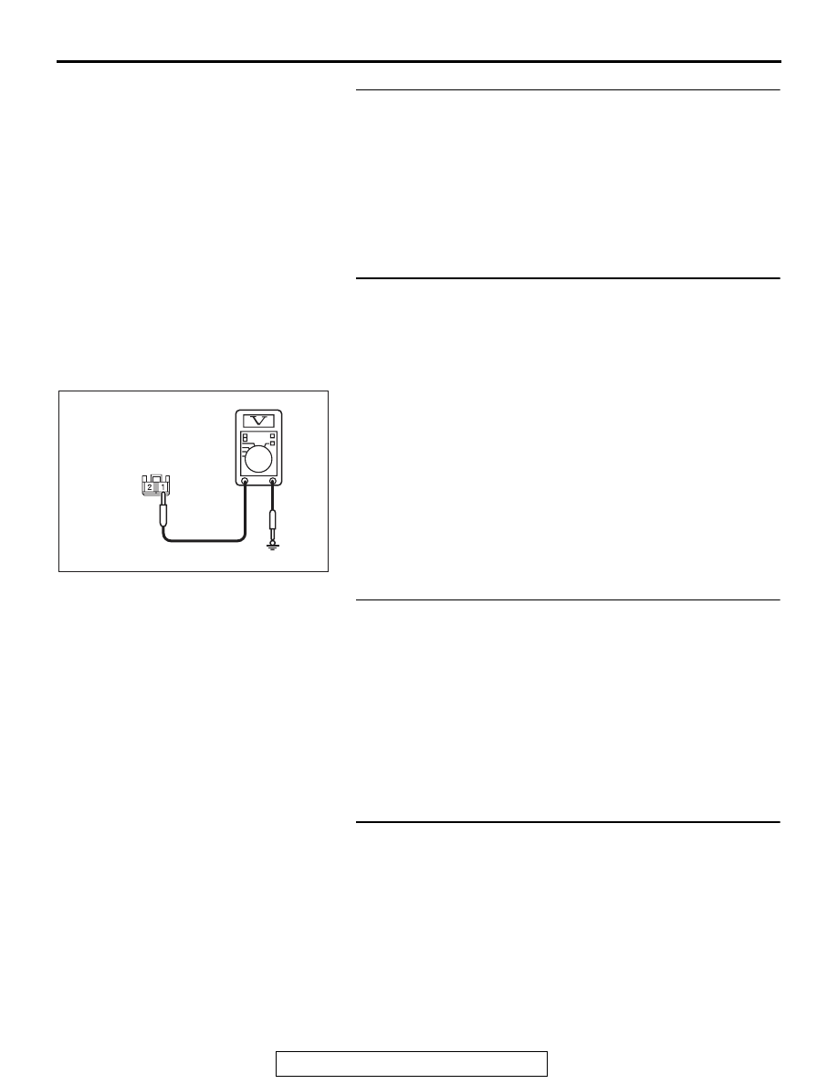
STEP 5. Check the fusible link (34) line of power supply 
circuit to the ETACS-ECU. Measure the voltage at 
ETACS-ECU connector C-309.
(1) Disconnect ETACS-ECU connector C-309 and measure the 

voltage available at the wiring harness side of the 
connector.

(2) Measure the voltage between terminal 1 and ground.

• The voltage should measure approximately 12 volts 

(battery positive voltage).

Q: Is the measured voltage approximately 12 volts (battery 

positive voltage)?
YES : 
Go to Step 7.
NO :  Go to Step 6.

STEP 6. Check the wiring harness between ETACS-ECU 
connector C-309 (terminal 1) and fusible link (34).
Q: Is the wiring harness between ETACS-ECU connector 

C-309 (terminal 1) and fusible link (34) in good 
condition?
YES : 
No action is necessary and testing is complete.
NO :  The wiring harness may be damaged or the 

connector(s) may have loose, corroded or damaged 
terminals, or terminals pushed back in the connector. 
Repair the wiring harness as necessary. Check that 
the power window works normally.

STEP 7. Check ETACS-ECU connector C-307 for loose, 
corroded or damaged terminals, or terminals pushed back 
in the connector.
Q: Is ETACS-ECU connector C-307 in good condition?

YES : Go to Step 8.
NO :  Repair or replace the damaged component(s). Refer 

to GROUP 00E, Harness Connector Inspection 

P.00E-2

. Verify that the power window works 

normally.

AC208730BI

Connector C-309 
(harness side)

DOOR

TSB Revision

BODY

42A-72

STEP 8. Check the fusible link (36) line of power supply 
circuit to the ETACS-ECU. Measure the voltage at 
ETACS-ECU connector C-307.
(1) Disconnect ETACS-ECU connector C-307 and measure the 

voltage available at the wiring harness side of the 
connector.

(2) Measure the voltage between terminal  2 and ground.

• The voltage should measure approximately 12 volts 

(battery positive voltage).

Q: Is the measured voltage approximately 12 volts (battery 

positive voltage)?
YES : 
Go to Step 10.
NO :  Go to Step 9.

STEP 9. Check the wiring harness between ETACS-ECU 
connector C-307 (terminal 2) and fusible link (36).
Q: Is the wiring harness between ETACS-ECU connector 

C-307 (terminal 2) and fusible link (36) in good 
condition?
YES : 
No action is necessary and testing is complete.
NO :  The wiring harness may be damaged or the 

connector(s) may have loose, corroded or damaged 
terminals, or terminals pushed back in the connector. 
Repair the wiring harness as necessary. Check that 
the power window works normally.

STEP 10. Check power window main switch connector 
E-15 for loose, corroded or damaged terminals, or 
terminals pushed back in the connector.
Q: Is power window main switch connector E-15 in good 

condition?
YES : 
Go to Step 11.
NO :  Repair or replace the damaged component(s). Refer 

to GROUP 00E, Harness Connector Inspection 

P.00E-2

. Verify that the power window works 

normally.

AC208730BJ

Connector C-307
(harness side)

DOOR

TSB Revision

BODY

42A-73

STEP 11. Check the ETACS-ECU connector C-315 line 
circuit to the power window main switch. Measure the 
voltage at power window main switch connector E-15.
(1) Disconnect power window main switch connector E-15 and 

measure the voltage available at the wiring harness side of 
the connector.

(2) Measure the voltage between terminal 5 and ground.

• The voltage should measure approximately 12 volts 

(battery positive voltage).

Q: Is the measured voltage approximately 12 volts (battery 

positive voltage)?
YES : 
Go to Step 14.
NO :  Go to Step 12.

STEP 12. Check ETACS-ECU connector C-315 for loose, 
corroded or damaged terminals, or terminals pushed back 
in the connector.
Q: Is ETACS-ECU connector C-315 in good condition?

YES : Go to Step 13.
NO :  Repair or replace the damaged component(s). Refer 

to GROUP 00E, Harness Connector Inspection 

P.00E-2

. Verify that the power window works 

normally.

STEP 13. Check the wiring harness between ETACS-ECU 
connector C-315 (terminal 10) and power window main 
switch connector E-15 (terminal 5).
NOTE: Also check intermediate connector C-128 for loose, cor-
roded, or damaged terminals, or terminals pushed back in the 
connector. If intermediate connector C-128 is damaged, repair 
or replace the damaged component(s) as described in GROUP 
00E, Harness Connector Inspection 

P.00E-2

.

Q: Is the wiring harness between ETACS-ECU connector 

C-315 (terminal 10) and power window main switch 
connector E-15 (terminal 5) in good condition?
YES : 
No action is necessary and testing is complete.
NO :  The wiring harness may be damaged or the 

connector(s) may have loose, corroded or damaged 
terminals, or terminals pushed back in the connector. 
Repair the wiring harness as necessary. Check that 
the power window works normally.

AC208730 BP

Connector E-15
(harness side)

DOOR

TSB Revision

BODY

42A-74

STEP 14. Check the ground circuit to the power window 
main switch. Measure the resistance at power window 
main switch connector E-15.
(1) Disconnect power window main switch connector E-15 and 

measure the resistance available at the wiring harness side 
of the connector.

(2) Measure the resistance value between terminal 10 and 

ground.

• The resistance should be 2 ohms or less.

Q: Is the measured resistance 2 ohms or less?

YES : Go to Step 16.
NO :  Go to Step 15.

STEP 15. Check the wiring harness between power 
window main switch connector E-15 (terminal 10) and 
ground.
NOTE: Also check intermediate connector C-128 for loose, cor-
roded, or damaged terminals, or terminals pushed back in the 
connector. If intermediate connector C-128 is damaged, repair 
or replace the damaged component(s) as described in GROUP 
00E, Harness Connector Inspection 

P.00E-2

.

Q: Is the wiring harness between power window main 

switch connector E-15 (terminal 10) and ground in good 
condition?
YES : 
No action is necessary and testing is complete.
NO :  The wiring harness may be damaged or the 

connector(s) may have loose, corroded or damaged 
terminals, or terminals pushed back in the connector. 
Repair the wiring harness as necessary. Check that 
the power window works normally.

STEP 16. Retest the system.
Check that the all power windows work.
Q: Is the check result normal?

YES : No action is necessary and testing is complete.
NO :  Replace ETACS-ECU. Check that the power window 

works normally.

AC209731

AC208731CA

Connector E-15
(harness side)


Content   ..  490  491  492  493   ..