Mitsubishi Evolution X. Manual - part 487


  Index      Mitsubishi     Mitsubishi Evolution X - service repair manual 2008 year


Search            


Content   ..  485  486  487  488   ..


Mitsubishi Evolution X. Manual - part 487


DOOR

TSB Revision

BODY

42A-51

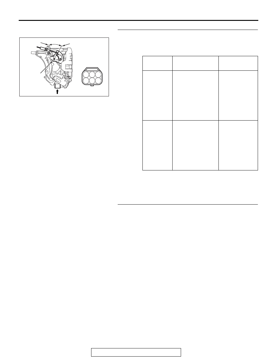
STEP 11. Check the rear door lock actuator (RH).
Remove the rear door lock actuator (RH). The illustration 
shows when the door lock actuator is viewed from inside the 
door. Refer to 

P.42A-129

.

Q: Is the rear door lock actuator (RH) normal?

YES : Go to Step 12.
NO :  Replace the rear door lock actuator (RH). Verify that 

all the doors can be locked and unlocked normally.

STEP 12. Check ETACS-ECU connector C-311 for loose, 
corroded or damaged terminals, or terminals pushed back 
in the connector.
Q: Is ETACS-ECU connector C-311 in good condition?

YES : Go to Step 13.
NO :  Repair or replace the damaged component(s). Refer 

to GROUP 00E, Harness Connector Inspection 

P.00E-2

. Verify that all the doors can be locked and 

unlocked normally.

Lever 
position

Battery 
connection

Lever 
operation

At the 
"LOCK" 
position

• Connect 

terminal No.4 
and the negative 
battery terminal.

• Connect 

terminal No.6 
and the positive 
battery terminal.

The lever moves 
from the "LOCK" 
position to the 
"UNLOCK" 
position.

At the 
"UNLOCK" 
position

• Connect 

terminal No.6 
and the negative 
battery terminal.

• Connect 

terminal No.4 
and the positive 
battery terminal.

The lever moves 
from the 
"UNLOCK" 
position to the 
"LOCK" 
position.

AC609755

4

2
5

3
6

1

A

AB

Lever

UNLOCK

LOCK

View A

DOOR

TSB Revision

BODY

42A-52

STEP 13. Check the wiring harness between ETACS-ECU 
connector C-311 (terminals Nos. 6 and 9) and rear door 
lock actuator (RH) connector E-19 (terminals Nos. 6 and 4).
NOTE: Also check joint connector (4) C-43, intermediate con-
nector D-01 for loose, corroded, or damaged terminals, or ter-
minals pushed back in the connector. If joint connector (4) 
C-43, intermediate connector D-01 is damaged, repair or 
replace the damaged component(s) as described in GROUP 
00E, Harness Connector Inspection 

P.00E-2

.

Q: Is the wiring harness between ETACS-ECU connector 

C-311 (terminals No. 6 and 9) and rear door lock 
actuator (RH) connector E-19 (terminals No. 6 and 4) in 
good condition?
YES : 
Go to Step 18.
NO :  The wiring harness may be damaged or the 

connector(s) may have loose, corroded or damaged 
terminals, or terminals pushed back in the connector. 
Repair the wiring harness as necessary. Verify that all 
the doors can be locked and unlocked normally.

STEP 14. Check rear door lock actuator (LH) connector 
E-26 for loose, corroded or damaged terminals, or 
terminals pushed back in the connector.
Q: Is rear door lock actuator (LH) connector E-26 in good 

condition?
YES : 
Go to Step 15.
NO :  Repair or check the connector. Refer to GROUP 00E, 

Harness Connector Inspection 

P.00E-2

. Verify that all 

the doors can be locked and unlocked normally.

DOOR

TSB Revision

BODY

42A-53

STEP 15. Check the rear door lock actuator (LH).
Remove the rear door lock actuator (LH). The illustration shows 
when the door lock actuator is viewed from inside the door. 
Refer to 

P.42A-129

.

Q: Is the rear door lock actuator (LH) normal?

YES : Go to Step 16.
NO :  Replace the rear door lock actuator (LH). Verify that 

all the doors can be locked and unlocked normally.

STEP 16. Check ETACS-ECU connector C-311 for loose, 
corroded or damaged terminals, or terminals pushed back 
in the connector.
Q: Is ETACS-ECU connector C-311 in good condition?

YES : Go to Step 17.
NO :  Repair or replace the damaged component(s). Refer 

to GROUP 00E, Harness Connector Inspection 

P.00E-2

. Verify that all the doors can be locked and 

unlocked normally.

Lever 
position

Battery 
connection

Lever 
operation

At the 
"LOCK" 
position

• Connect 

terminal No.4 
and the negative 
battery terminal.

• Connect 

terminal No.6 
and the positive 
battery terminal.

The lever moves 
from the "LOCK" 
position to the 
"UNLOCK" 
position.

At the 
"UNLOCK" 
position

• Connect 

terminal No.6 
and the negative 
battery terminal.

• Connect 

terminal No.4 
and the positive 
battery terminal.

The lever moves 
from the 
"UNLOCK" 
position to the 
"LOCK" 
position.

AC609754

4

2
5

3
6

1

A

AB

Lever

UNLOCK

LOCK

View A

DOOR

TSB Revision

BODY

42A-54

STEP 17. Check the wiring harness between ETACS-ECU 
connector C-311 (terminals Nos. 6 and 9) and rear door 
lock actuator (LH) connector E-26 (terminals Nos. 6 and 4).
NOTE: Also check joint connector (4) C-43, intermediate con-
nector D-24 for loose, corroded, or damaged terminals, or ter-
minals pushed back in the connector. If joint connector (4) 
C-43, intermediate connector D-24 is damaged, repair or 
replace the damaged component(s) as described in GROUP 
00E, Harness Connector Inspection 

P.00E-2

.

Q: Is the wiring harness between ETACS-ECU connector 

C-311 (terminals Nos. 6 and 9) and rear door lock 
actuator (LH) connector E-26 (terminals Nos. 6 and 4) in 
good condition?
YES : 
Go to Step 18.
NO :  The wiring harness may be damaged or the 

connector(s) may have loose, corroded or damaged 
terminals, or terminals pushed back in the connector. 
Repair the wiring harness as necessary. Verify that all 
the doors can be locked and unlocked normally.

STEP 18. Retest the system.
Check that the central door locking system works normally.
Q: Is the check result normal?

YES : No action is necessary and testing is complete.
NO :  Replace the ETACS-ECU. Check that the central door 

locking system normally.


Content   ..  485  486  487  488   ..