Mitsubishi Evolution X. Manual - part 477
FENDER
TSB Revision
BODY
42A-11
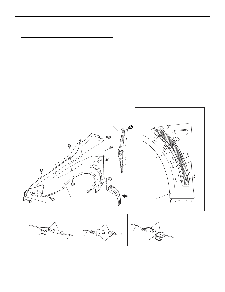
FENDER
REMOVAL AND INSTALLATION
M1421001901208
Pre-removal and post-installation operation
• Front splash shield removal and installation (Refer to
• Side air dam removal and installation (Refer to GROUP
51, Side Air Dam
.)
• Front bumper bracket removal and installation (Refer to
GROUP 51, Front Bumper Assembly and Radiator Grille
.)
• Front delta garnish removal and installation (Refer to
GROUP 51, Garnish and Molding
.)
• Front deck garnish removal and installation (Refer to
GROUP 51, Windshield Wiper
.)
• Headlight assembly removal and installation (Refer to
GROUP 54A, Headlight
• Side turn signal light removal and installation (Refer to
GROUP 54A, Side Turn Signal Light
AC705330AB
1
3
1
4
4
D
A
B
B
B
B
C
C
D
B
B
D
4
4
2
D
D
D
B
B
D
D
C
C
Section B – B
Section C – C
Section D – D
View A
Claw
Claw
Clip
1
1
1
4
Removal steps
<<
A
>> >>
A
<< 1. Fender
2. Fender protector rear
3. Front fender bracket
4. Front fender garnish
Removal steps (Continued)