Mitsubishi Evolution X. Manual - part 408
DIAGNOSIS <TC-SST>
TSB Revision
TWIN CLUTCH- SPORTRONIC SHIFT TRANSMISSION (TC-SST)
22C-89
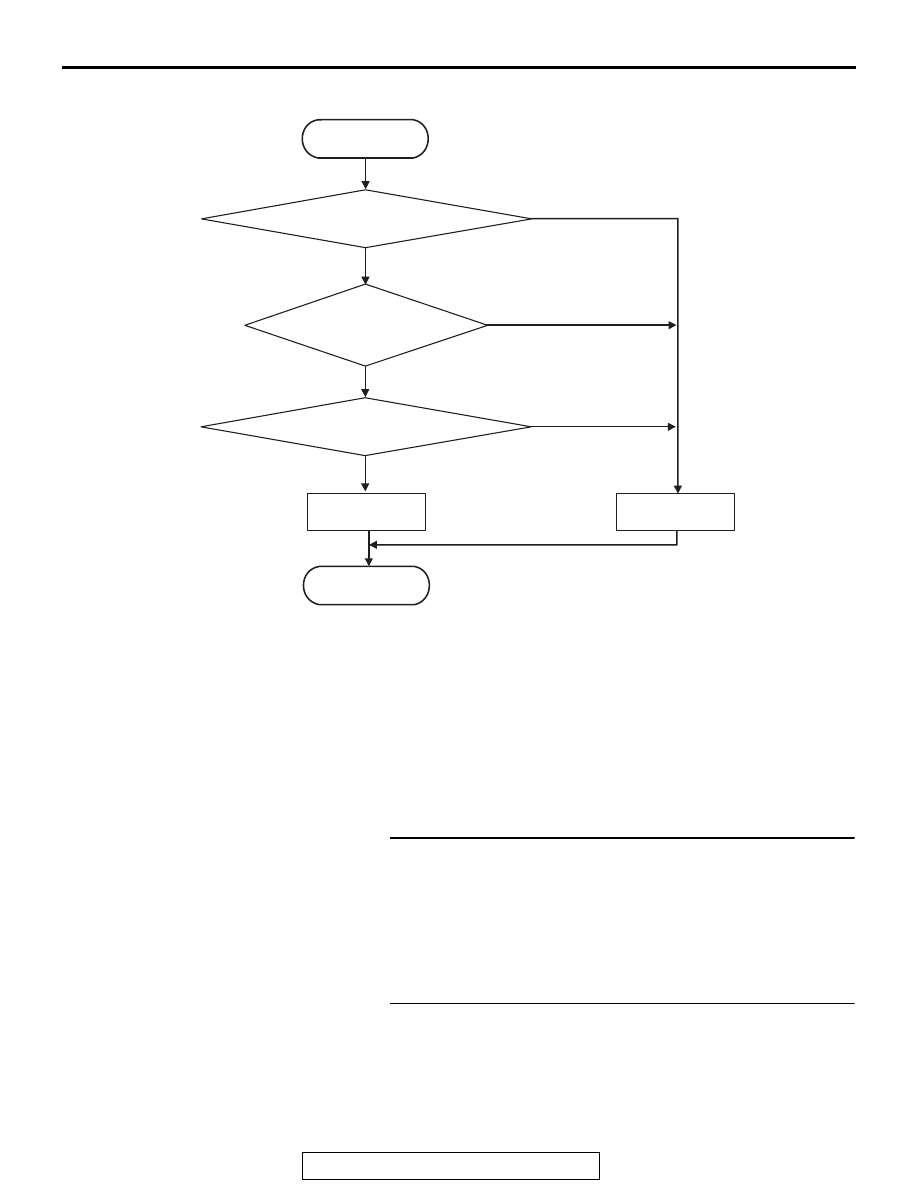
LOGIC FLOW CHARTS (Monitor Sequence)
.
DTC SET CONDITIONS
Check Conditions
• Voltage of battery: 8 V or more.
• Voltage of battery: 16.5 V or less.
JUDGMENT CRITERIA
• Supply voltage: 3.07 V or less. (140 millisecond)
.
OBD-II DRIVE CYCLE PATTERN
The supply voltage remains 3.07 V or more for 140
milliseconds.
.
PROBABLE CAUSES
• Malfunction of TC-SST-ECU
DIAGNOSTIC PROCEDURE
STEP 1. Scan tool CAN bus diagnostics
Using scan tool MB991958, diagnose the CAN bus lines.
Q: Is the check result normal?
YES : Go to Step 2.
NO : Repair the CAN bus lines. (Refer to GROUP 54C
−
Troubleshooting
.) After repairing the CAN
bus line, go to Step 2.
STEP 2. Check whether the DTC is reset.
Q: Is DTC No. P1806 set?
YES : Replace the TC-SST assembly. (Refer to
NO : Intermittent malfunction. (Refer to GROUP 00
− How
to Cope with Intermittent Malfunction
.)
AC710669
START
No
Good
Malfunction
END
Monitoring condition met
Continuous failure
for 140 msec
No
Yes
Yes
Yes
No
Sensor supply < 3.07 V