Mitsubishi Evolution X. Manual - part 402
DIAGNOSIS <TC-SST>
TSB Revision
TWIN CLUTCH- SPORTRONIC SHIFT TRANSMISSION (TC-SST)
22C-65
DTC P0967: Clutch Cooling Flow Solenoid System (Short to power supply)
CAUTION
• If there is any problem in the CAN bus lines,
an incorrect diagnostic trouble code may be
set. Prior to this diagnosis, diagnose the CAN
bus lines.
• Whenever the ECU is replaced, ensure that
the CAN bus lines are normal.
.
DIAGNOSTIC FUNCTION
TC-SST-ECU checks that the clutch cooling flow
solenoid circuit is normal.
.
DESCRIPTIONS OF MONITOR METHODS
The clutch cooling flow solenoid circuit is determined
to be short to power supply.
.
MONITOR EXECUTION
• Continuous
.
MONITOR EXECUTION CONDITIONS
(OTHER MONITOR AND SENSOR)
Other Monitor (There is no temporary DTC stored
in memory for the item monitored below)
• P0776: Clutch cooling flow solenoid system
(Drive current range out)
• P0777: Clutch cooling flow solenoid system
(Stuck)
• P0964: Clutch cooling flow solenoid system
(Open circuit)
• P0965: Clutch cooling flow solenoid system
(Overvoltage)
• P0966: Clutch cooling flow solenoid system
(Short to ground)
Sensor (The sensor below is determined to be
normal)
• Not applicable
.
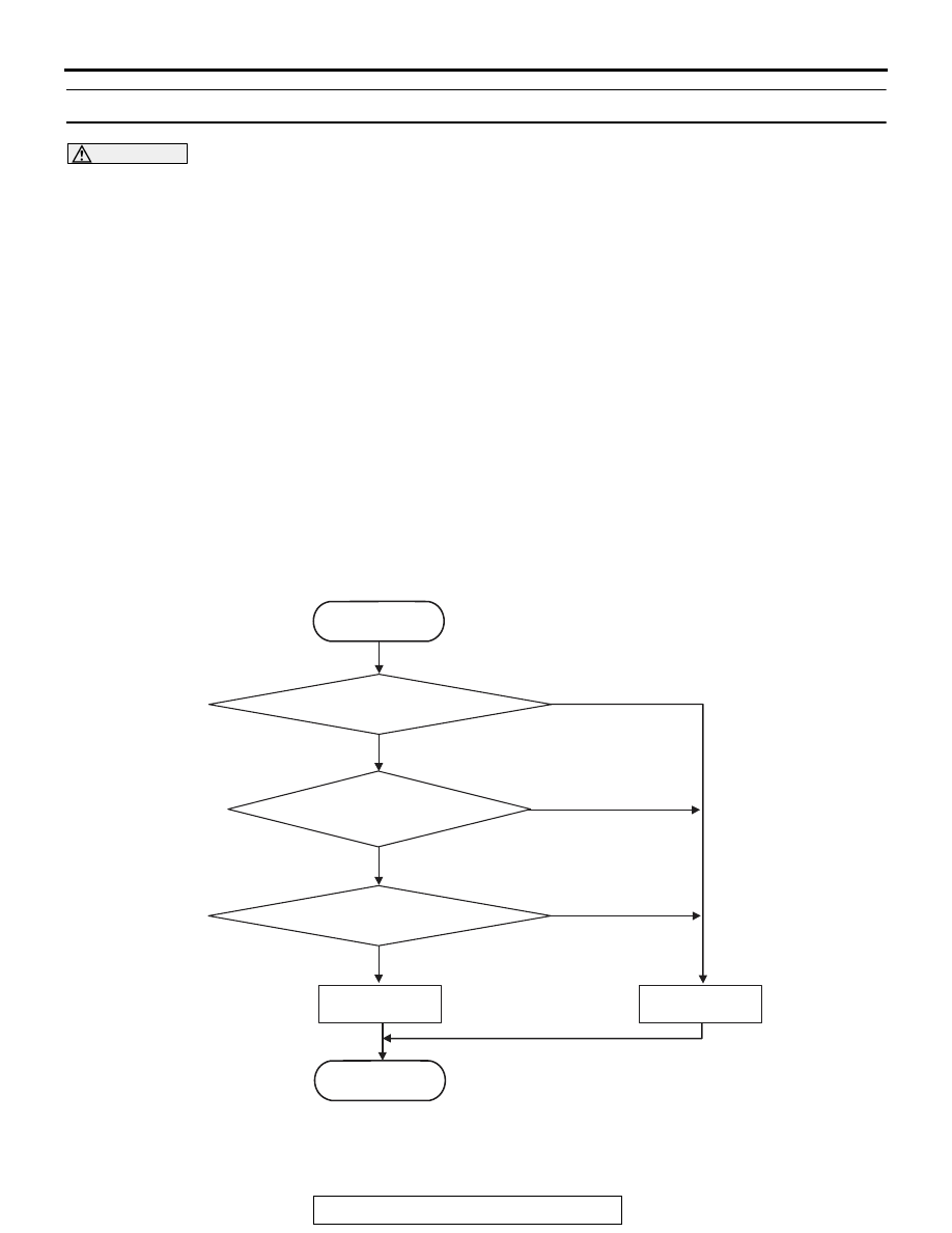
LOGIC FLOW CHARTS (Monitor Sequence)
.
AC710638
START
No
Yes
Good
Malfunction
END
Monitoring condition met
Continuous failure
for 5 sec
No
Yes
No
Yes
FET* output
> Battery voltage - 2 V
*FET : Field Effect Transistor